A simple circuit can improve the dynamic performance of a phototransistor for use in low- to medium-speed applications as fast as 100 kbps, such as optical isolation of an RS-232C serial line (Figure 1). In low-cost applications that require high voltage insulation, low part count, and low power, you can use consumer components, such as SFH421 IR LED with an SFH320 IR phototransistor. The rise/fall-time rating of the LED is 500 nsec, which is fast enough, but the phototransistor's rise/fall time is 5 µsec for the fastest version and 8 µsec for the slowest with a 1-kilohm load.
 |
|
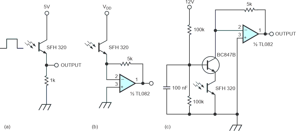
| Figure 1. | A basic phototransistor (a) has a 5- to 8-μsec rise/fall time with a 1-k. resistor. An op amp can improve a phototransistor’s response time (b) but performs poorly without additional phase compensation. Alternatively, you can use a transistor to isolate the phototransistor’s capacitance and to hold the signal voltage across the phototransistor to a stable dc value (c). |
Phototransistors have less favorable dynamic behavior than do photodiodes because, in addition to the collecting and charging processes, phototransistors also experience a delay stemming from the amplification mechanism (Miller effect). For the rise and fall time of a phototransistor, the following relationship applies:
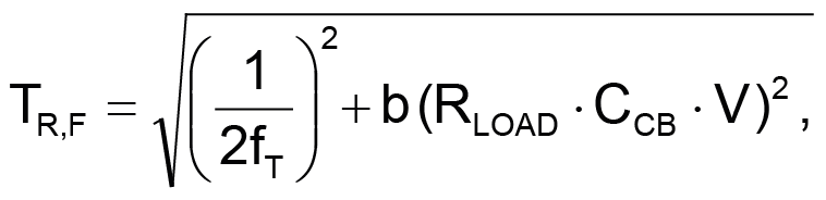
where fT is the transition frequency, CCB is the collector-base capacitance, V is the gain, and b is a constant whose value lies between 4 and 5. For RLOAD = 1 kΩ, 4 < b < 5, 100 < V < 1000, CCB ≈ 2.5 pF, and fT ≈ 100 kHz, the result is 5 µsec < TR,F < 8 µsec.
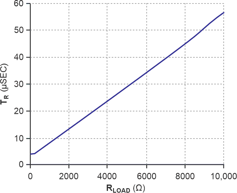
A plot of rise time TR vs load resistance RLOAD provides a more practical way to evaluate the maximum transmission speed of Figure 1a's circuit without using additional compensation circuitry (Figure 2). For a 2400 bps serial link with less than 10% error on the bit length, the rise-time estimate is 42 µsec, which corresponds to a 7.5-kilohms resistor.
 |
|
| Figure 2. | The relationship between worst-case rise time and load resistance for the basic phototransistor circuit indicates that for a TR of 42 μsec, RLOAD should equal 7.5 kΩ. |
To get a faster response time, you can use an op amp, but without phase compensation the result is poor. In Figure 1b's circuit, the phototransistor's internal capacitance and the amplifier's gain bandwidth limit the overall speed. To cancel the side effect of the phototransistor's CCB, the amplifier needs a small capacitor in parallel with R. Choosing the right value for the compensation capacitor is a difficult task, because the current-to-voltage converter exhibits a two-pole response. Also, to ensure stability, you need to consider phase compensation and bandwidth together.
Fortunately, there is another way to get the best of the phototransistor bandwidth. You can isolate the phototransistor's internal capacitance with a transistor (Figure 1c). The transistor, with its low output impedance and its large gain bandwidth, holds the signal voltage across the phototransistor to a stable dc value. The versatile BC847 can do the job, and, with SFH320, the circuit can reach a transmission speed of 153.6 kbps. You can't increase the speed beyond this point, even with the fastest op amp, because of the photoelectric delay that the charging and collecting processes cause.