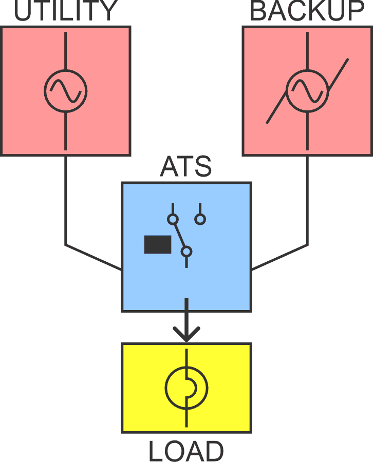
In today’s world, both households and industrial facilities are exploring ways to improve power reliability by harnessing multiple energy sources, not just the electricity from the grid. One clever solution: Automatic transfer switch (ATS).
An ATS is a clever piece of hardware that automatically shifts the electrical load from your primary power supply to a backup or standby source – like a generator – when it detects an outage. The result? A stable, uninterrupted power supply that keeps critical appliances and operations humming along. In Figure 1 is a quick visual to help you understand the system better.
 |
|
| Figure 1. | Here is how an ATS shifts the electrical load from primary power supply to a backup or standby source. |
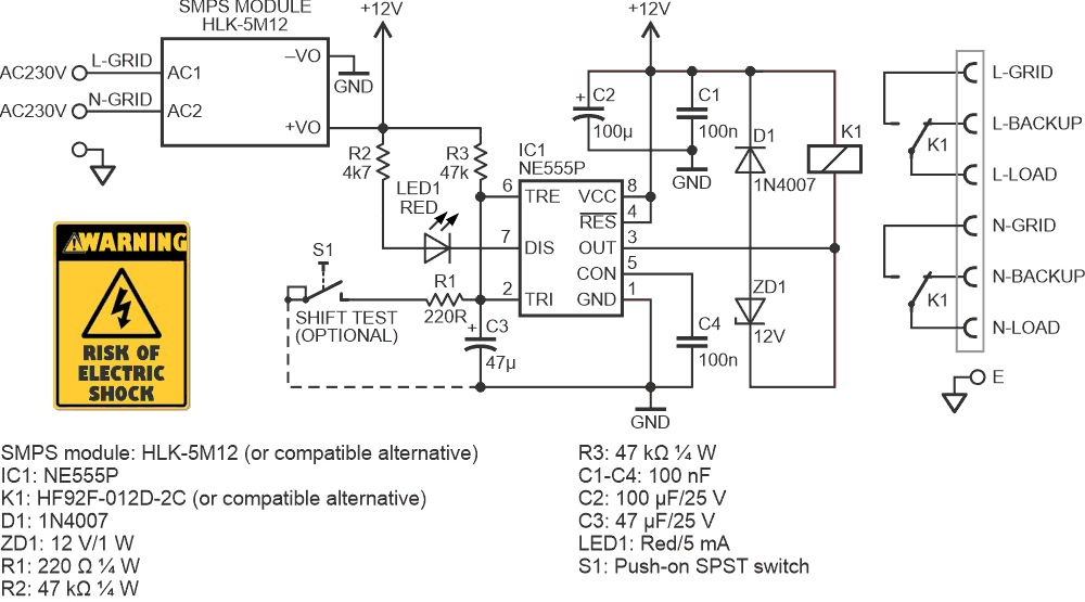
If you are searching for a reliable ATS but want to avoid overpriced commercial models or sketchy low-end options, this post is for you. The tried-and-true preliminary schematic In Figure 2 shows you how to design and build your own ATS using a handful of analog components you may already have in your parts bin.
 |
|
| Figure 2. | The schematic shows an ATS built from a handful of analog components. |
The circuitry is stripped down to its bare essentials.
The NE555P timer (IC1) handles the automatic transfer switch function, with its activation delay set to approximately 2.4 seconds using a 47-kΩ resistor (R3) and a 47 μF capacitor (C3).
The way that it works is simple. When the circuit is first powered on, the power relay (K1) remains off briefly. Following the activation delay, pin 3 of IC1 goes low, triggering the relay and transferring the load supply from the backup source to the grid.
Bear in mind that when the voltage at pins 2 and 6 is above 2/3 of the supply voltage, the output pin 3 goes Low, activating the relay. The duration of this delay is primarily decided by the RC time constant of components R3 and C3. To set the delay, you can apply the formula t = 1.1 × R3 × C3.
While the delay mechanism may initially appear redundant, it ensures the load connects only once grid stability is restored following a blackout (an electrical surge may occur when grid power is restored after an outage).
LED1 can be used to indicate the switching states, whereas the optional button switch (S1) can be used to test the shift function by hand.
Moreover, with the 12-V Zener diode (ZD1) in place, the relay releases more quickly than it otherwise would. As is well known, a Zener diode wired in series with a reverse-biased flyback diode across the relay coil clamps the BEMF at a higher voltage, accelerating coil current decay and enabling faster relay release.
Just to note, the HLK-5M12 is a compact, PCB-mountable 12 V/5 W AC-DC SMPS module ideal for embedded applications, and the design presented here is tailored around it. Though almost any similar power module with matching specifications can be used in its place.
So, this simple system functions entirely automatically – presence and absence of the primary power source toggles the switching mechanism. Obviously, this ‘open-delayed’ transition system is designed for applications that can tolerate brief delays of a few milliseconds (primarily induced by the operating time and release time of the power relay).
It’s good to remember that a typical transfer switch setup connects an electric utility service and a generator to provide both normal and emergency power, forming what’s commonly known as an emergency standby generator system.
Also, transfer switches shift loads between normal and emergency power sources using either open or closed transition methods. In an open transition (break-before-make), the switch disconnects from one power source before connecting to the other (variants include open-delayed and open in-phase transitions). In contrast, a closed transition (make-before-break) briefly connects both power sources before disconnecting the first, ensuring uninterrupted power delivery to downstream loads during the transfer.
While a self-built ATS offers a clear advantage in terms of cost, that is where its edge ends. Both versions can handle the task effectively, but a commercial-grade switch brings to the table robust safety features, precision engineering, and reliability that is expected in professional settings – justifying its higher price tag. That said, for aboveboard applications, the homemade version delivers dependable performance with minimal fuss and a much lighter impact on your wallet.
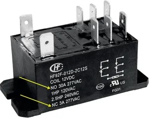
A few more notes on the power relay: When selecting a power relay for mains switching, it must handle both mains voltage and several amperes, ideally with some current margin for reliability. To ensure full galvanic isolation between the input circuits, both the live (L) and neutral (N) lines should be switched. This calls for a 2 Form C (DPDT) relay configuration. The ground (earth) connections, however, must remain continuously connected.
It’s also crucial to note that most power relays are rated for significantly higher current on their normally open (NO) contacts compared to their normally closed (NC) contacts, sometimes differing by order of magnitude (see Figure 3). In an ATS, both contact sets need to be capable of handling relatively high current, as both paths are actively involved in switching loads. So, you will want to dig in a bit to find the right power relay, and you might need to tweak the relay driver circuit to get it just right.
 |
|
| Figure 3. | Most power relays are rated for significantly higher current on normally open contacts compared to normally closed contacts. |
This is a bare-bones ATS without extra features like power filter, power monitor, synchronized transfer, and generator switch. It’s on hold for a rollout in an upcoming, advanced design iteration, at least for now.