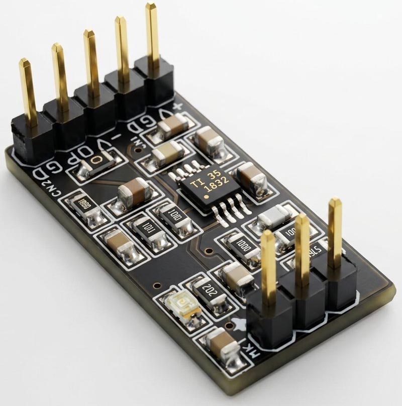
This 3-wire microphone pre-amplifier in Figure 1 is designed using the low-power, low-noise, and low-distortion OPA1692 audio operational amplifier, making it ideal for high-performance electret microphone applications. The circuit is optimized for electret microphones that use a 3-wire interface, providing excellent audio quality while maintaining minimal power consumption.
 |
|
| Figure 1. | 3-wire electret microphone pre-amplifier. |
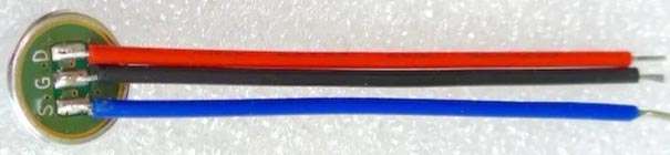
The primary application of this pre-amplifier is in wireless microphone systems, where high audio fidelity and long battery life are essential. A typical wireless microphone (Figure 2) consists of an electret microphone element, an analog pre-amplifier stage, and a transmission circuit that may use either analog or digital communication methods.
 |
|
| Figure 2. | A typical wireless microphone. |
Since wireless microphones are usually battery-powered, power efficiency is a critical design requirement. The OPA1692-based pre-amplifier delivers clean signal amplification with very low noise and distortion while consuming minimal power, helping to extend battery life without compromising audio performance. This makes it well suited for portable audio equipment, wireless microphones, voice communication devices, and other battery-operated audio applications.
Credits: Schematic from Texas Instruments applications, user must refer the data sheet of OPA1692 op-amp for details information,
Features
- Power Supply ±5 V DC
- Current consumption less than 1.5 mA (without LED)
- Maximum sound level pressure (SPL) 120 dB
- On board power LED
- Bandwidth 20 Hz to 20 kHz
- Gain 11.79 V/V or 21.43 dB
- PCB dimensions: 25.88 × 13.34 mm
Schematic
 |
|
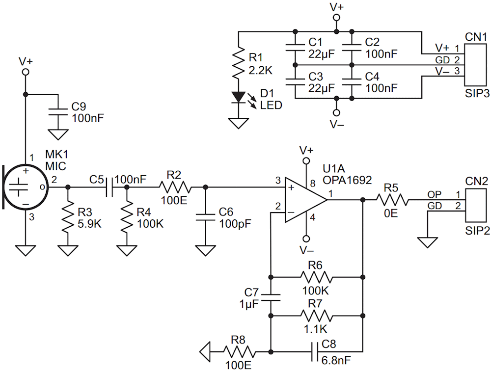
| Figure 3. | Schematic diagram of the pre-amplifier. |
Figure 3 shows the schematic diagram of the electret microphone pre-amplifier. Table 1 shows the bill of materials.
| Table 1. | List of circuit components | |||||||||||||||||||||||||||||||||||||||||||||||||||
|
||||||||||||||||||||||||||||||||||||||||||||||||||||
Connections
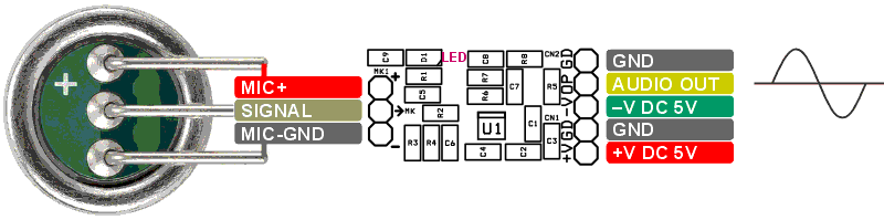
Figure 4 shows the pre-amplifier connection diagram.
 |
|
| Figure 4. | The pre-amplifier connection diagram. |