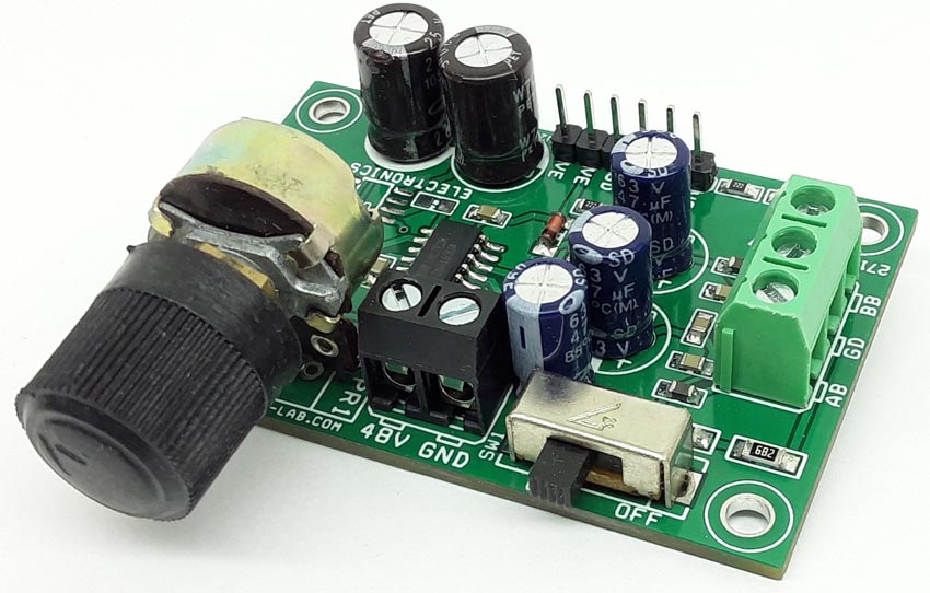
The project presented here is a professional quality phantom powered microphone pre-amplifier (Figure 1). The project is built using the INA163 chip from TI. The Chip is a very low-noise, low-distortion, monolithic instrumentation amplifier. R2 and R3 provide a current path for a conventional 48 V phantom power source for a remotely located microphone. A slide switch SW1 allows phantom power to be disabled. C6 and C8 block the phantom power voltage from the INA163 input circuitry. Additional input protection against ESD and hot-plugging, four 1N4148 diodes D1, D2, D3, D4 connected from the input to supply lines. R7 and R8 provide a path for the input bias current of the INA163. Gain is set with a variable resistor, PR1, in series with R4. R4 determines the maximum gain. The total resistance, R4 + PR1, determines the lowest gain. A special reverse-log taper potentiometer for PR1 can be used to create a linear change (in dB) with rotation. LED D5 is used as a power indicator. L1, L2, C7, C10, and C11 components protect the inputs from EMI and RFI noise.
 |
|
| Figure 1. | Schematic diagram of a phantom powered microphone preamplifier. |
Optional DC output control loop
Input offset current (typically 100 nA) creates a DC differential input voltage that will produce an output offset voltage. This is generally the dominant source of the output offset voltage. With a maximum gain of 1000 (60 dB), the output offset voltage can be several volts. This may be entirely acceptable if the output is AC-coupled into the subsequent stage. An optional circuit is provided to tackle this problem. An inexpensive FET-input op-amp U2A in a feedback loop drives the DC output voltage to 0 V. Op-amp is not in the audio signal path and does not affect signal quality.
To add an additional DC output control loop you need to do the following:
- U2A = OPA2134 SOIC8
- C9 = ceramic capacitor 0.1 µF/50 V SMD size 0805
- R6 1 MΩ 5% SMD resistor size 0805
- Omit resistor R5
Connections and other details
- CN1: pin 1 = +48 V DC phantom power Input, Pin 2 = GND
- CN2: pin 1-2 = VCC +15 V DC, Pin 3-4 = GND, Pin 5-6 VEE –15 V DC
- CN3: pin 1 = BB microphone – VIN, Pin 2 = GND, Pin 3 = AB microphone + VIN
- CN4: pin 1 = audio output, Pin 2 = GND
- D5: power LED
- SW1: phantom power enable/disable switch
Note: Non-polarized capacitors should be used for C6 and C8 if phantom power is to be disabled.
Features
- Power supply dual 15 V DC (±15 V DC)
- On board power LED
- Slide switch for phantom power enable/disable
- 3 pin screw terminal for microphone connections
- 2 pin screw terminal for audio output
- 2 pin screw terminal for phantom power input 48 V DC
- 6 pin male header for power input
- Gain up to 1000 V/V (60 dB)
- Potentiometer PR1 gain adjust
- PCB dimensions 60.17 × 39.85 mm
- 4 × 3 mm mounting holes
Figure 2 shows the amplifier connection diagram.
 |
|
| Figure 2. | The amplifier connection diagram. |
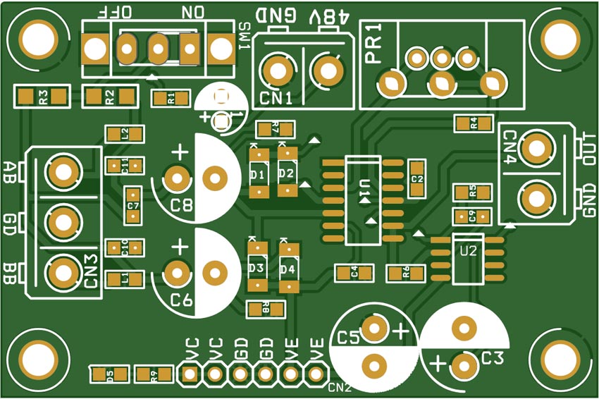
The Gerber project files can be downloaded from the link in the Downloads section. The PCB layout is shown in Figure 3.
 |
|
| Figure 3. | The PCB layout. |