Finally second and improved AVR DDS signal generator is here. First AVR DDS V1.0 generator was only an attempt of running DDS algorithm without any amplitude control. This time I still wanted to keep things simple like minimum count of widely accessible components circuit, single sided PCB that comes together with good functionality.
AVR DDS specification
AVR DDS signal generator V2.0 is a firmware based DDS signal generator which uses slightly modified Jesper’s DDS algorithm adapted to AVR-GCC C program as in-line ASM. Signal generator has two outputs – one for DDS signal and another for high speed [1..8MHz] square signal – which may be used for reliving microcontrollers with wrong fuse settings or for other purposes as well. High speed (HS) signal is direct output from Atmel Atmega16 OC1A(PD5) pin. DDS output is used for all other signals that are generated via R2R resistor network and is adjusted via LM358N offset and amplitude regulating circuits. Offset and amplitude can be regulated by two potentiometers. Offset can be regulated in range +5V..-5V while amplitude in range 0..10V. DDS frequency range is from 0 to 65534Hz that is more than enough for testing audio circuits and other tasks.
Main AVR DDS V2.0 signal generator features:
- Simple circuit with easily accessible and cheap components;
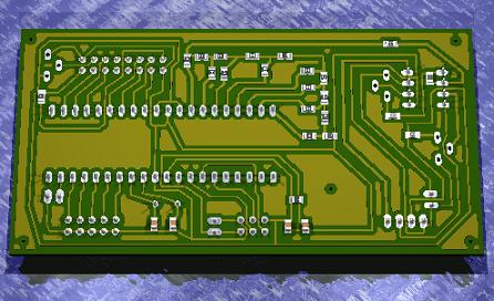
- Single sided PCB;
- In box power supply with external AC plug;
- Dedicated high speed (HS) signal output up to 8MHz;
- DDS signal with variable amplitude and offset;
- DDS signals: sine, square, saw, rev saw, triangle, ECG and noise.
- 2×16 LCD menu;
- Intuitive 5 button keypad.
- Frequency adjusting steps: 1, 10, 100, 1000, 10000Hz;
- Restoring last configuration after power up.
In the block diagram you may see logical structure of signal generatorV2.0
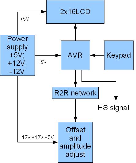
As you can see device requires several voltages: +5V, -12V, +12V, GND. -12V and +12V are used for offset and amplitude control. In this case power supply is constructed by using simple transformer and few voltage regulators.
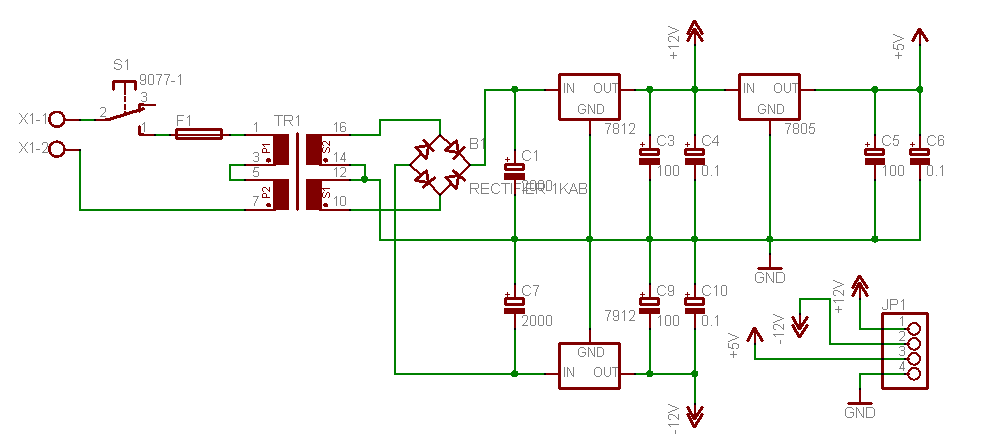
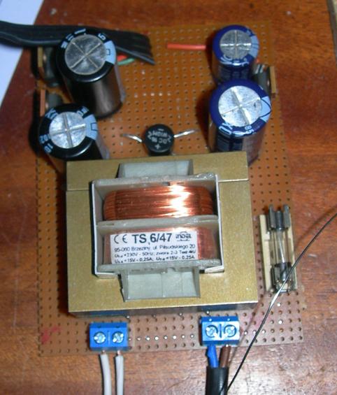
Power supply block is assembled on a separate prototyping PCB board.
If you do not want to build power supply you may use PC ATX power supply unit where all required voltages are available. You may need to modify molex connector wiring as follows:

Circuit diagram and PCB
Circuit diagram of DDS generator (excluding power supply) is very simple with easy accessible components. It uses following parts:
- AVR Atmega16 microcontroller clocked with 16MHz external crystal;
- Standard HD44780-based 2×16 LCD module;
- R2R DAC made of simple resistors;
- LM358N low power dual op amplifier;
- Two potentiometers;
- 5 buttons;
- several connectors and sockets.
Circuit diagram and PCB:

Single sided PCB:
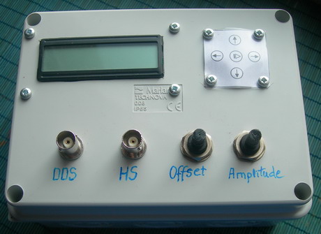
Assembly
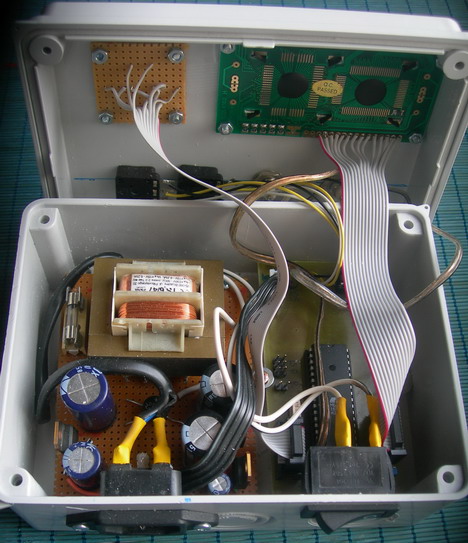
DDS generator is assembled in to plastic box:
Downloads
EagleCAD schematic and PCB
Proteus simulation files with latest firmware included
In the second part of article we will consider algorithm of work of the microcontroller and its basic differences from the version which author is Jesper Hansen, понакомимся with an operating procedure and menu options. Images of the form of a signal with DDS an exit of the generator removed by means of an oscillograph will be besides given.
New implementation of the AVR DDS signal generator v2.0