Introduction
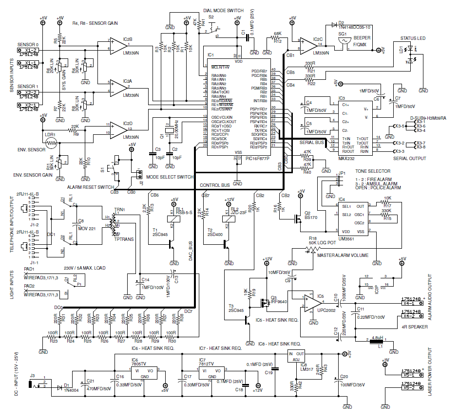
In this project we design low cost high performance programmable home security system using few LDR's as an input sensors. When above sensor(s) get triggered system may dial the user specified phone number (using build-in DTMF generator) and activate the high power audio alarm and lights. All the parameters of DTMF generator, audio alarm and light interface are programmed through the RS232 serial interface.
Current firmware of this system presents interactive control system through the RS232 interface. This control system consist with the menu driven configuration options, self tests, system report generators, etc.
This system also contain 5W (with 4Ω speaker) audio alarm with three selectable tone configurations, which include Police siren, Fire engine siren and Ambulance siren.
System Features
- Touch tone phone dialing interface
- 5W High powerful audio alarm
- 2 sensor interface with separate sensitivity adjustments
- Programmed through the RS232 interface
- Build-In intelligent light ON/OFF switch
Integrated Circuits
This system uses a Microchip's PIC16F877A as a main controller, LM339 as sensor interface, UM3561 as a tone generator and μPC2002 (TDA2002) as a speaker driver (audio amplifier). LM7805, LM7812 and LM317 voltage regulators are used to obtain +5V, +12V and +3V respectively.
Assembly
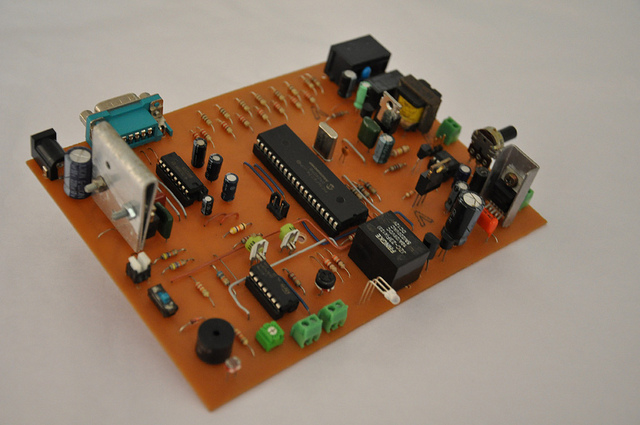
The PCB design given with this article makes the assembly much simpler. As PCB contain 230V AC main lines care must be taken while assembling the circuit. As shown in the fig.1 all the photoelectric sensors, some of the switches and alarm speaker are connected with the circuit through the connector bars.
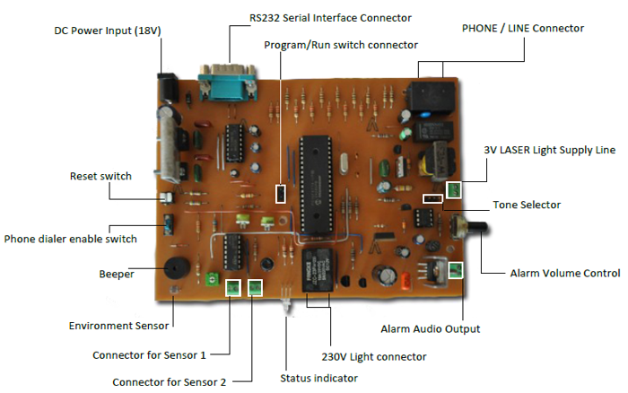
External connectors and controls
- DC Power input : Attach DC power supply with 18V - 25V (2A Max.) output.
- RS232 Connector : Connect RS232 serial cable to the port to configure the system. Do not use RS232 Null Modem cable with this port.
- PHONE/LINE connector : Attach standard RJ12/RJ11 telephone cable connector to this port. One port is need to use with the phone line and remaining port is for the phone (and it is optional).
- 3V LASER supply : 3V supply line for LASER diode assembly.
- Connectors for Sensor 1/2 : Attach high sensitive LDRs for these ports. To get the maximum sensitivity it is recommended to use EG&G VACTEC LDRs.
- Status Indicator : Indicate run, program and sensor trigger modes.
- Reset Switch : Press this button to reset entire alarm system. This button enable only when the audible alarm get activated. It is not possible to use this function at the phone dialing/ringer states.
- Phone dialer enable switch : Turn on this switch to enable the phone dialing feature of this system.
- Environment Sensor : In-circuit LDR to detect light conditions of the environment.
- Alarm Volume Control : Use this to control the output power (volume) of the audible alarm.
- 230V Light connector : Attach 230V AC light (or related peripheral) to these terminals.
- Tone Selector : Configure the master alarm tone from this jumper as follows,
- 1-2 : Fire Engine Siren
- 2-3 : Ambulance Siren
- Open : Police Siren (Do not connect jumper terminal 1-3, this combination may permanently damage the entire system)
- Beeper : Produce beeps (e.g: at the input error, etc.)
- Program / Run Switch connector : Attach switch to this header to select Program or Run mode.
- Alarm Audio Output : Attach 8Ω (8W) or 4Ω (10W) speaker to this connector.
Parts List
| IC1 | PIC16F877A |
| IC2 | LM339N |
| IC3 | MAX232 |
| IC4 | UM3561 |
| IC5 | μPC2002 |
| IC6 | LM7805 |
| IC7 | LM7812 |
| IC8 | LM317 |
| D1 | 1N4004 |
| D2 | 1N4148 |
| T1, T3 | 2SC945 |
| T2 | 2SD400 |
| Q1 | 20.00MHz Crystal |
| Q2 | BS170 |
| Q3 | IRF9640 |
| R4, R8 | 30K (LIN) Potentiometr |
| R6 | 20K (LIN) Potentiometr |
| R11 | 50K (LIN) Potentiometr |
| R18 | 50K (LOG) Potentiometr |
| R1, R2, R3, R19 | 10K |
| R5, R7, R9, R10 | 22K |
| R12 | 68K |
| R13, R14 | 2.2K |
| R15 | 330K |
| R16, R20 | 1K |
| R21, R22, R42 | 300Ohm |
| R23, R24, R25, R26, R27, R28, R29, R30 |
100Ohm |
| R31, R32, R33, R34, R35, R36, R37, R38 |
220Ohm |
| R39, R40, R41 | 47K |
| R43 | 240K |
| L1 | 4.8 uH Inductor |
| LDR1 | VT90N2 LDR |
| LD1 | 5mm Tri-Color LED |
| SPK | 8 Ohm (8W) or 4 Ohm (10W) Speaker |
| C1, C18, C19 | 0.1 uF (25V) |
| C2, C3 | 10 pF |
| C11 | 0.22 uF (100V) |
| C16, C17 | 0.33uF (50V) |
| C4, C5, C6, C7 | 1uF (50V) |
| C13, C14 | 1uF (100V) |
| C9 | 10uF (35V) |
| C10 | 1000uF (35V) |
| C12 | 220uF (35V) |
| C20 | 100uF (35V) |
| C21 | 470uF (35V) |
| TRN1 | 600Ohm:600Ohm Isolation Transformer |
| SG1 | F/QMX Buzzer |
| RL1 | Shinmei RSB-5-S |
| RL2 | FANGKE JZC-23F |
| S1 | B3F-10XX-push on switch |
| S2 | M251 SPDT micro switch |
Downloads
EAGLE project files – download
Download this project in .PDF format - скачать
Calibration and Testing in next part