Calibration and Testing
Once everything is assembled take following steps to calibrate the system,
- Remove IC1, IC2, IC3 and IC4 from the IC bases.
- Apply 18V ( to 22V Max.) DC source to the power connector (J3).
- Check the voltage between Pin12 (GND) and Pin3 of IC2. It need to be 4.8V - 5.1V DC.
- Check the voltage between GND and E$4 jumper. It need to be 11.7V - 12.3V DC.
- Check the voltage between Pin1 and Pin3 (GND) of JP1. It need to be 2.5V - 3.1 V
- If all the above Step 3, 4 and 5 are correct, disconnect the power supply and insert IC1, IC2, IC3 and IC4 in to the appropriate IC bases. Attach suitable speaker to the X4 and connect RS232 cable to the system.
- Close the jumper J2 (Program Mode) and power on the system.
- Download and install PuTTY on to the target computer and setup the "Serial" connection with 9600 baud rate.
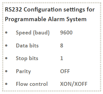
- Press "2" and enter into the "Parameter Setup" mode. Configure all the parameter options with the appropriate settings.
- Attach phone line to the PHONE/LINE connector and fix photoelectric LDR sensors to the X1 and X2 connectors.
- Press "3" and execute "Self Test".
- Adjust R4*, R6* and R8* preset controls, if the sensors are not trigged as expected.
- Adjust R11 preset to control the "Day" and "Night" mode detection.
- Open the Jumper J2 and press 5 to return to the Run mode.
- Shutdown the power supply and disconnect the RS232 cable.
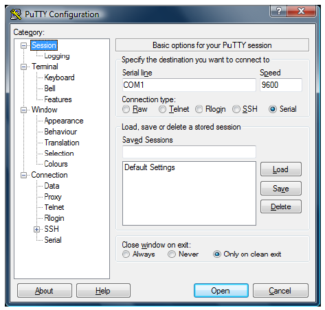
PuTTY configuration setup for Programmable Home Security Alarm System
* R6 - X1 sensor sensitivity, R8 - X2 sensor sensitivity, R4 - sensor gain controller (Common mode)
Downloads
Source Code - download