Electronic Design Europe 10.02.11
Yossi Barkan
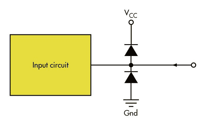
Some systems require a voltage limiter to protect the input circuit. Designers can connect diodes to VCC and Gnd to create a simple solution (Fig. 1). This simplicity, however, comes at a disadvantage: the input circuit can see voltages within a range of Gnd – VD up to VCC + VD.
 |
|
| Figure 1. | A very simple overvoltage protection technique uses diodes connected to VCC and Gnd. |
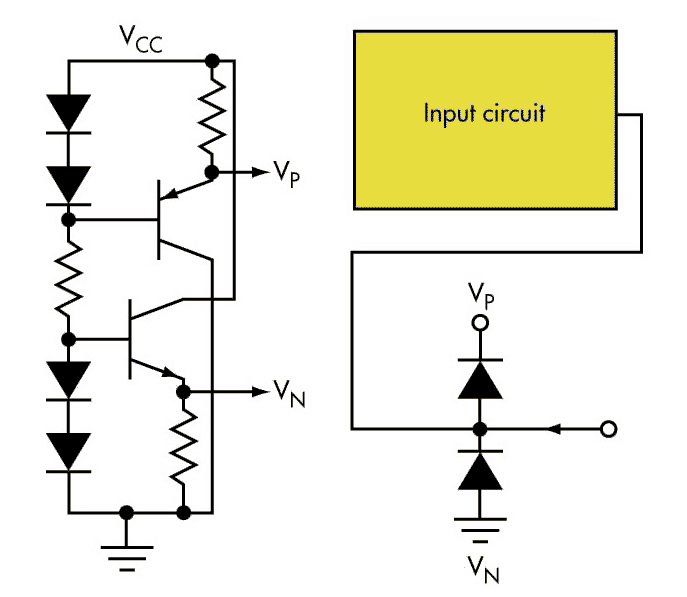
If the circuit is sensitive and can handle only voltages between Gnd and VCC, the circuit in Figure 2 is a better alternative. The improved limiter includes circuitry to generate two voltage power supplies:
VP = VCC – VD
which can sink current, and:
VN = Gnd + VD
which can source current.
The circuit assumes that VD = VBE. In this case, the protection diodes at the input will clamp the input voltage at no more than VCC and no less than Gnd.
 |
|
| Figure 2. | A better limiter generates VP and VN, which can be common to all the protection diodes on the same printed-circuit board. |