Jeff Kotowski
EDN
A power-meter circuit typically requires either an analog or a digital multiplying circuit. These circuits can be complex, finicky, or expensive. A simpler way to achieve the multiplication first converts the current to a duty cycle proportional to the current. You can use this duty cycle to gate the input voltage; the gating effectively provides a multiplication function. A lowpass filter then provides an output voltage proportional to power. The method sounds convoluted, but the implementation is simple.
 |
||
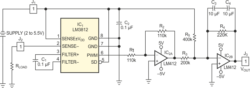
| Figure 1. | A low-cost duty-cycle IC forms the heart of a power-meter circuit. | |
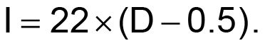
Figure 1 shows the complete power-meter circuit. The LM3812M-7.0 IC senses current and delivers a duty cycle proportional to the current. The current relates to the duty-cycle (D) output as follows:
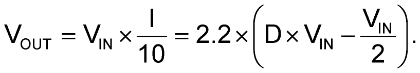
The desired output is a voltage equal to the input power divided by 10. The divide-by-10 operation keeps the voltage within a manageable range. The output is, then:
To subtract the ½VIN term in the equation, the first op amp inverts the power signal. The second op amp adds in the offset and again inverts the signal. Capacitors C1 and C2 provide filtering. These capacitors connect back-to-back to achieve nonpolar operation. Tests with input currents of –7 to +7 A and with a source voltage of 2 to 5.25 V showed better than 3% accuracy over the range of 0 to 25 W.