Embedded
After my previous review of more traditional ways of reducing the I/O lines needed to drive LEDs/displays and keyboards/switches, here I'm looking at the nominally new method of Charlieplexing.
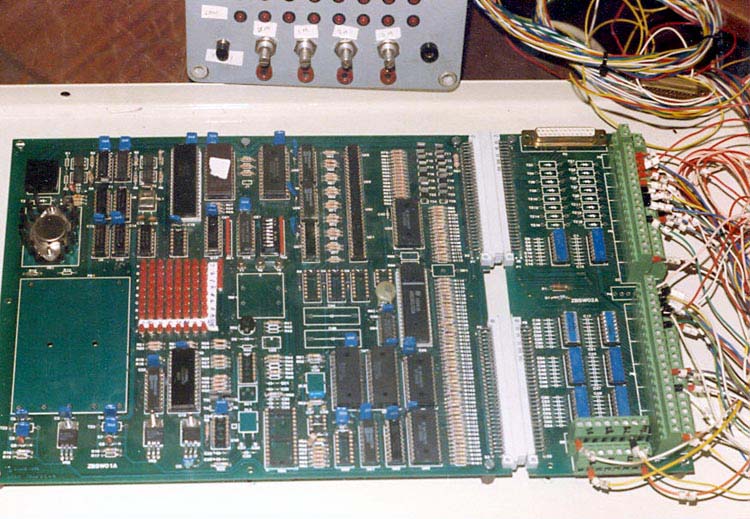
Back in about 1982, I was asked to design a product that had 72 individual LEDs (see Figure 1). I solved the problem by using an ICM7218, which allowed for individual segment control of eight 7-segment displays, so I simply treated each LED as one of the segments. The eight remaining LEDs were driven from the micro (if I remember correctly). That would have taken up 24 IC pins.
 |
|
| Figure 1. | An 8051-based product with 72 LEDs arranged in a matrix – the red blur you see in the middle of the board. |
As luck would have it, the solution that would have helped appeared long after I had completed the project. Charlieplexing was introduced in the 1990s (apparently its roots actually go back to quite a bit before that) by Charlie Allen at Maxim, it set the electronics world atwitter (in the 1990s sense) and there were quite a few design ideas published around this concept.
 |
|
| Figure 2. | Three pins controlling six LEDs as per the Charlieplexing technique. |
The Charlieplex idea was to use the bipolar drivers on the I/O lines so that the pin could source or sink a current. But an I/O pin also has an “off” state where it is high impedance or in read mode. If we analyze the simple arrangement in Figure 2 we can see that if P0 is logic high (and sourcing current), P1 is low (and sinking current) and P2 is in a read state (and in high impedance) LED DS1 will be illuminated. The six possible cases can be seen in Table 1.
| Table 1. | Possible combinations. | ||||||||||||||||||||||||||||
|
|||||||||||||||||||||||||||||
The LEDs need current limiting and when they are all the same type, the three resistors shown in Figure 2 will suffice. If you are using different LEDs then each LED will need its own series resistor. The electrical properties of the LEDs ensure that they are undamaged and only one is illuminated. The reverse voltage across any LED is clamped to the forward voltage of the paralleled LED and will be within the maximum reverse voltage rating of the LED. When two series LEDs are forward biased, the voltage is clamped by the single LED in parallel across them and the voltage will be insufficient for the pair to turn on.
The number of LEDs that can be controlled by this technique is calculated as N x (N–1) where N is the number of lines. Now to me this is back to front and you really want to know how many lines you need for a given number of LEDs. I don’t need to tell a bunch of engineers that you need to solve the quadratic equation, but Table 2 lists the relationship at smaller numbers.
| Table 2. | Relationship between the number of pins, number of LEDs and the duty cycle for each LED. |
||||||||||||||||||||||||||||||
|
|||||||||||||||||||||||||||||||
I thought to myself, now let’s expand the circuitry to more lines, and then… well my mind boggled. How do you set about doing this systematically? I turned to trolling the Internet and came up with this technique [1], which I will realize with 6 pins.
First draw the lines from the IC out horizontally including the resistors. Then add N–1 diode pairs (5 in this case) to the first row as you see in Figure 3a.
 |
|
| Figure 3a. | Six IC wires and five LED pairs on the first wire. |
Copy the LED pairs down to each wire below, reducing the number of pairs from the right resulting in Figure 3b.
 |
|
| Figure 3b. | Copying the LED pairs removing the pairs to the right of the diagonal. |
Finally connect from the bottom wire to all the LED pairs in the left column followed by the next wire up to the next column to the right until you are complete as you see in Figure 3c.
 |
|
| Figure 3c. | The completed Charlieplex hardware solution. |
App note [2] from Maxim shows how to connect 7 segment displays with a common cathode.
As is the way of the world, Charlieplex is not a complete panacea. As you can see from Table 2, the duty cycle gets really slim. In itself this is not a problem, but you have to scale up the current to get to the same average current for a particular brightness, and the absolute maximum ratings for the LED may stymie you, as we discussed in my previous article. And LED characteristics may not be the limiting factor – the microcontroller pins may be unable to source/sink the magnitude of currents required. It may be possible to improve performance using additional hardware as discussed in the design ideas [3] and [4].
The high refresh rate and the lookup translation may also pose a burden to the execution time of the host micro especially if you are using a dot matrix display. Maxim makes Charlieplexing ICs that offload the scanning and lookup providing some relief (the IC numbers are included in the above app note).
Charlieplexing is also an option for keyboard scanning, keeping in mind that the switch, when closed, will conduct in both directions, so that if you want the maximum number of switches you will need a series diode with each switch. Figure 4 shows a three-pin, six-switch solution.
 |
|
| Figure 4. | A familiar Charlieplex configuration for switches. |
All the pins must be configured for pull-ups, or there should be external ones. The micro sets each pin as an output in sequence, while maintaining the others as inputs. For each output in turn, it is set to low and all the inputs are checked to see if they have been pulled low. Based on the input/output pair, the active button can be decoded.
Over this series of articles we have covered several methods of reducing the pin count while monitoring switches and driving LEDS. The world has got more complex and now there are multicolor LEDs. One solution to reducing the number of I/O lines required is the shift register approach of the Worldsemi WS2811 as described by our inimitable Max in [5]. Do you have any other methods to add? Is Charlieplexing in your future?