Alan Walsh, Analog Devices
Precision measurement is extending into application areas that require greater and greater power efficiency. This is particularly true with the advent of IoT, which is driving greater need for wireless sensor nodes with precision measurement capability, battery-powered wearable fitness/ medical devices, and industrial signal chains that use isolated power, 4 mA to 20 mA loop-powered or battery-powered field instruments. In these scenarios, greater power efficiency means longer battery lives with less maintenance as well as simplified power supply design.
Typically, precision measurement systems use low dropout regulators (LDOs) as part of their power supply schemes to generate low noise rails for precision ADCs. However, LDOs can be very inefficient in delivering power and often the majority of power is lost in the LDO dissipated as heat. This article discusses a means of achieving a higher efficiency power solution for your precision successive approximation register (SAR) ADC. This is achieved by using an ultralow power switching regulator in a hysteretic mode and analyzing the performance trade-offs – including a means to intelligently control the switching regulator synchronous to the SAR conversion to improve noise performance.
Fixed frequency or pulse-width modulated (PWM) switching regulators provide a very efficient (often >90%) means of generating voltage rails in a measurement system at medium to high load currents (hundreds of mA to multiple A). However, this efficiency comes at the cost of switching ripple that is usually at a fixed frequency of hundreds of kHz to a couple of MHz. As seen in Figure 1, the power supply rejection ratio (PSRR) of a typical precision SAR ADC is very good at low frequencies up to ~100 kHz – beyond this the PSRR drops off rapidly.
 |
||
| Figure 1. | SAR ADC analog power supply rejection vs. frequency. | |
Typical load currents to supply the VDD line of a precision SAR ADC are in the couple mA range or μA if the ADC is run at a lower throughput – so there are no efficiency benefits in using a fixed frequency switcher to supply the ADC directly instead of an LDO.
However, high efficiency, ultralow power step-down switching regulators can be operated in a hysteretic mode with very low quiescent current.
In hysteresis mode, the regulator charges the output voltage slightly higher than its nominal output voltage with PWM pulses by regulating the constant peak inductor current. When the output voltage increases until the output sense signal exceeds the hysteresis upper threshold, the regulator enters standby mode. In standby mode, the high-side and low-side MOSFETs and a majority of the circuitry are disabled to allow a low quiescent current as well as high efficiency performance, as seen in Figure 2. During standby mode, the output capacitor supplies energy into the load, and the output voltage decreases until it falls below the hysteresis comparator lower threshold. The regulator wakes up and generates the PWM pulses to charge the output again.
 |
||
| Figure 2. | PWM (top) and hysteretic mode (bottom) – efficiency vs. load current. |
|
In the hysteretic case, the switching ripple frequency is a function of the load current and LC network and for loads of a couple mAs is in the kHz range. At a few kHz, the PSRR of the precision ADC is very good and will do a good job of rejecting/attenuating the switching ripple at the ADC digital output.
 |
||
| Figure 3. | AD7980 and ADP5300 application circuit. | |
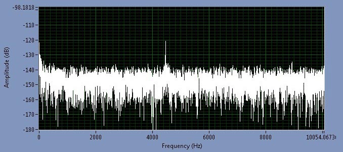
Take for example the circuit shown in Figure 3 with the AD7980 ADC; its VDD current consumption is typically 1.5 mA at full throughput (1 MSPS) and scales linearly as you decrease the throughput. As can be seen in Figure 4, the switching frequency ripple is 4.5 kHz and 50 mV peak-to-peak on a 2.5 V regulated output from a 5 V rail. This ripple is attenuated at the ADC digital output by the PSRR rating of the ADC. In the ADC FFT output it shows up as a spur of magnitude –120 dBFS at 4.5 kHz. For a 5 V input range on the ADC, this equates to
This level of ripple showing up in the ADC output is extremely low for a 16-bit converter; 5 μV peak-to-peak corresponds to 0.07 LSB at 16 bits. Ripple at this level is buried in the ADC noise floor and requires a large amount of averaging to uncover it and will not be seen in many applications. This output ripple corresponds to a PSRR of

 |
||
 |
||
| Figure 4. | ADP5300 hysteretic switching ripple (ac-coupled) when supplying the AD7980 and ripple tone in ADC FFT output at 1 MSPS throughput. |
|
This measurement is similar to what is shown in Figure 1 for the AD7980 PSRR of ~77 dB at 4.5 kHz.