Introduction
Battery-powered electronics poses multiple challenges to the power system engineer. At a theoretical level, the battery related circuitry (before DC/DC conversion) may be divided into four functions: power selection, charging (for rechargeable batteries), monitoring and protection. Power selection prioritizes between the multiple power sources typically available in a battery-powered system, e.g., wall adapter, USB port and internal battery, whereas the charging circuit needs to be customized to the specific battery chemistry. Monitoring circuitry reports battery voltage, charge, and temperature status, which used alongside a battery protection circuit, ensures higher reliability. In this article, we will explore the features and benefits provided by a new micropower battery protection device, ideal for battery applications ranging from automotive, medical to consumer applications.
Considerations When Designing with Battery Power
Even simple battery related problems, not just fires and explosions, can tarnish a product’s reputation. Therefore, attention needs to be paid to the design of battery related safety features. Batteries come with their charge and discharge current ratings; exceeding these ratings heats up the battery, which not only reduces the life of the battery but explodes it in the worst case. Overcurrent protection may be implemented with fuses, but fuses are bulky, slow to react and have wide tolerances in their trip threshold (Figure 1). To prevent irreparable damage, rechargeable batteries need to be disconnected before going into deep discharge. For a 3.7 V Li-Ion cell, this level is around 2.5 V. An undervoltage lockout (UVLO) circuit is needed to disconnect the battery from the load. This may be implemented with a comparator, reference voltage, and a solid-state switch. A P-channel MOSFET high-side switch doesn’t need a charge pump to turn it on, lowering battery current drain, but P-channel MOSFETs have limited selection and cost more than N-channel MOSFETs for the same on-resistance. Conversely, a more efficient N-channel MOSFET low-side switch may be used if the ground line can be floated. The undervoltage threshold needs to have sufficient hysteresis; otherwise, the UVLO circuit will oscillate off-on-off since battery voltage recovers after load turn-off.
 |
||
| Figure 1. | A Possible Battery & Load Protection Discrete Circuit | |
After battery protection, we need to consider load protection. Transient voltage suppressors implement overvoltage protection during brief conditions such as ringing, spikes and surges, but burn up during sustained or DC overvoltages (OV). Therefore, another comparator is needed to protect the load from an input overvoltage. If a battery is misinserted with reversed polarity, the load may be damaged if it cannot tolerate negative voltages. A series diode is used to block the negative voltage. But, this diode dissipates power and drops significant voltage during forward operation.
As seen, a bunch of discrete components and circuits are needed to implement comprehensive protection for battery-powered systems. At the same time, the quiescent current consumption of these circuits needs to be kept low so that battery run- and standby-time is not shortened. For example, automotive electronic modules have a standby current budget of less than 100 μA to prevent battery discharge while a car is parked for a few weeks. For high current dissipating circuits, a relay may be used to disconnect them from the battery. Relays are also used to turn the load on and off but relays are bulky, preventing form-factor reduction. A more efficient and simpler protection method is needed.
Low Quiescent Current Solution for Battery Power Control & Protection
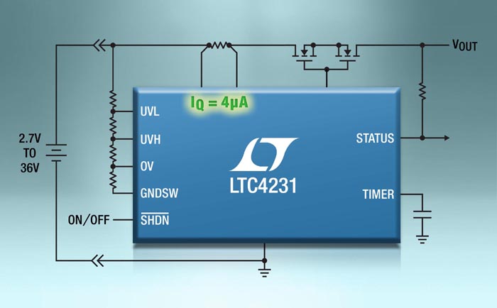
The LTC4231 is an ultralow quiescent current (IQ) hot swap controller, enabling safe insertion and extraction of boards or batteries in 2.7 V to 36 V systems (Figure 2). The 2.7 V to 36 V operating range accommodates a wide range of battery chemistries including lead-acid, Li-Ion, and stacked NiMH, NiCad or alkaline.
 |
||
| Figure 2. | LTC4231 Hot Swap Controller & Electronic Circuit Breaker Consumes Just 4 μA of Quiescent Current, Ideal for Battery-Powered Systems. |
|
The LTC4231 controls external low-loss N-channel MOSFETs to gently power up board capacitors, avoiding sparks, connector damage, and system glitches. Soft-start and inrush current level is easily adjusted with a resistor-capacitor connected to the MOSFET gate. During normal operation (pass MOSFETs fully on), dual level overcurrent protection is provided by a timed circuit breaker and fast current limit. For minor overloads, a fault timer is activated; when it expires, the MOSFETs are opened to disconnect the load. During heavy overloads or an output short-circuit, the fault timer is activated and load current is limited to 60% above the circuit breaker threshold. Depending on the option, the LTC4231 either stays off after an overcurrent fault or automatically turns on after a 500 ms cool-down period.
Undervoltage protection cuts off low voltage batteries to prevent deep discharge, while adjustable hysteresis avoids oscillations from battery recovery after load removal. Input overvoltage disconnects the load, preventing damage. The LTC4231 survives and also protects downstream circuitry from reversed batteries up to –40 V by controlling back-to-back N-channel MOSFETs (Figure 3). A single MOSFET is sufficient if reverse input protection is not needed.
 |
||
| Figure 3. | When a reversed battery is inserted, e.g., –24 V at IN, the LTC4231 protects the load by blocking the negative voltage from propagating to the output (OUT). Back-to-back MOSFETs (shown in Figure 2) are needed for reverse input protection. |
|
Even with all this functionality, device quiescent current is a mere 4 μA during normal operation; placing the LTC4231 in shutdown mode reduces its IQ to 0.3 μA and turns off the external N-channel power MOSFETs to disconnect downstream circuits, extending battery standby time. To ensure low current operation, the undervoltage and overvoltage resistive dividers are connected to a strobed ground, lowering their average current draw by 50x.
Techniques to Lower Quiescent Current
 |
||
| Figure 4. | To lower quiescent current, LTC4231 activates the charge pump periodically to refresh the MOSFET gate voltage as needed. |
|
The LTC4231 employs two innovative techniques to lower its current consumption during normal operation while providing protection that is indistinguishable from other current-hungry controllers. To turn on the external N-channel MOSFETs and lower their on-resistance, the LTC4231 uses an internal charge pump to generate a gate voltage at least 10 V above the input voltage. In other controllers, the charge pump works continuously even after the gate is driven on, essentially idling but contributing significantly to quiescent current consumption. In contrast, the LTC4231 turns off the charge pump after the MOSFET gate reaches its peak voltage. If the gate voltage sags due to leakage, the charge pump turns on to deliver a pulse of charge, refreshing the gate voltage. This is shown in Figures 4 and 5 for example gate leakages of 0.1 μA and 1 μA. This technique reduces charge pump current consumption by a factor of 50x to 100x as the charge pump on current is 200 μA but drops to 2 μA in sleep mode.
 |
||
| Figure 5. | The MOSFET gate voltage refresh rate is shown for two different gate leakage examples (ΔVGATE is GATE-to-SOURCE voltage, ICC is LTC4231’s current consumption). |
|
The second technique to lower LTC4231’s quiescent current is to sample the input voltage every 10 ms to determine if it has gone below the undervoltage threshold or above the overvoltage threshold. A strobed ground connection (GNDSW) is provided for the external input voltage resistive divider (Figure 6). The occasional sampling lowers the resistive divider’s current consumption by 50x, which is the sampling period (10 ms) divided by the sampling window (200 μs). The comparators monitoring the UVL, UVH, and OV pins are turned on during the sampling window, lowering their average current consumption also by 50x. The 10 ms sampling period works well for batteries since their voltage changes slowly over time. However, if the undervoltage or overvoltage condition occurs at start-up, the LTC4231 holds the MOSFETs off to block the out-of-range voltage from propagating to the load.
 |
||
| Figure 6. | The input voltage is monitored in a 200 μs window every 10 ms (2% duty cycle) to lower UV/OV monitoring current consumption by 50x. During the sampling window, GNDSW is connected to GND by an internal 80 Ω switch. |
|
Conclusion
Most emerging electronic applications – wireless sensors, fitness trackers, augmented reality glasses, drones, robots – are battery powered, for reasons of functionality, portability and convenience. Energy-dense batteries such as Li-Ion have brought the issue of battery safety into the public eye. The LTC4231 provides a simple, compact and rugged micropower solution for hot plugging and battery protection, especially in energy conscious applications, protecting the system against battery deep discharge, output overload or short-circuit, overvoltage and reverse battery connections.