Rien Oortgiesen, Jens Tybo Jensen, Infineon Technologies
Traditional class D amplifiers present significant design challenges in compact applications such as portable consumer sound systems and smart speakers. These challenges include relatively low efficiency, high heat generation even at low to medium listening levels, and a need for bulky and costly filters to reduce out of band noise.
A relatively new range of class D amplifiers address these limitations using so-called multilevel amplification. This approach improves power consumption while inherently reducing interference and out of band noise. In addition, manufacturing costs are reduced by eliminating or minimizing the use of filters, which also helps save design space.
1 Introduction
In recent decades, switch-mode audio amplification has been the preferred method to bring an input audio signal to life. The various switch-mode amplifier topologies, known collectively as class D amplifiers, are popular due to their low power consumption, small size, and low heat generation – especially when compared to earlier class AB amplifiers.
Traditional class D amplifiers can achieve an efficiency of 90 percent or better at the highest output power. However, efficiency at typical music volume listening level is only around 50 or less. This and other limitations have inspired Infineon’s MERUS™ audio product designers to develop a new generation of amplifiers with high efficiency at all listening levels; the multilevel class D amplifier. This new class of amplifiers excel in applications that require small size, low heat dissipation, and/or low power consumption which is the case for an increasing number of compact and demanding audio applications.
1.1 Evolution of amplifier technology
Silicon semiconductor devices have been the subject for intensive research and development and for good reasons, class D amplifiers are now preferred for most portable and power-sensitive applications, replacing earlier linear amplifier classes such as class AB amplifiers. Although just as powerful in terms of output power capability, class AB amplifiers are significantly less efficient which means that they require large heatsinks and hence require too much space for the vast majority of audio applications.
The technological advancement from class AB amplifiers to class D amplifiers has been significant. Now, audio product designers are taking the next big leap in performance improvement, from traditional to multilevel class D amplifiers.
2 Traditional class D amplifiers
2.1 Traditional class D working principle
The working principle of the output stage of a traditional class D amplifier is shown in Figure 1. It consists of two power metal-oxide semiconductor field-effect transistors (MOSFETs, shown as M1 and M2 in Figure 1), each driven by a pulse-width-modulated (PWM) signal. The duty cycle of this PWM signal is modulated by the audio signal that is fed into the amplifier. This typically takes place inside a control loop.
 |
||
| Figure 1. | Traditional class D output stage. | |
The switch-node (VPWM) in Figure 1 transfers the amplified PWM signal. Note that an LC filter is used to smoothen the audio signal from the PWM signal before the amplified audio signal reaches the speaker. While this filter is not required for smaller applications such as mobile phones due to the low power output of the audio amplifier, applications would typically need an LC filter for output levels higher than around 20 W.
2.2 Traditional class D limitations
The limitations of traditional class D amplifiers include:
- Size due to the need for an LC filter and heatsink
- Cost due to the need for filters
- Inefficiency at typical listening levels
- Heat and thermally challenging operating conditions
2.2.1 Efficiency of about 50 percent at typical listening levels
Traditional class D amplifiers have a two-level power stage (half-bridge): meaning that each half-bridge can have the voltage potential of either 0 V or PVDD. Consequently, they have relatively high power consumption even in or near idle mode. In part, this is due to the inherent and constant rail-to-rail switching of each half-bridge which is required to maximize dynamic performance.
Figure 2 graphs the efficiency of a traditional class D amplifier. The horizontal axis is plotted on a logarithmic scale to emphasize the lower end of the output power scale. For typical listening levels of 0.1 to 1 W of output power per channel, efficiency barely reaches 50 percent. The headroom above 1 W is typically used to deliver the peak power which is required every now and then to accurately reproduce the music signal. Figure 2 shows that a traditional class D amplifier can reach 90 percent efficiency, but only for levels above 10 W (in this case, up to 40 W) – levels that are rarely reached by real-life audio signals for extended time-intervals.
 |
||
| Figure 2. | Efficiency of a traditional class D amplifier. | |
At the lower end of the power output scale, the overall efficiency is dominated by the power consumption (input power) of the amplifier in the idle condition – i.e. the power consumption of the amplifier when it is not producing any output.
 |
||
| Figure 3. | Input power for a traditional class D amplifier. | |
Figure 3 shows idle power consumption at close to 1 W for a conventional class D amplifier, which is running on an 18 V power rail. Due to the less than ideal curve shape, the audio amplifier easily dominates power consumption of the complete audio system – not just at high output volumes but even between idle and medium output volumes.
2.2.2 Bulk and cost issues
For traditional class D amplifiers, it is normal practice to apply a common-mode LC filter to reduce electromagnetic interference (EMI) and improve electromagnetic compatibility (EMC).
In addition, traditional class D designs may incorporate two extra resistor-capacitor (RC) networks which also increase the overall solution size:
- A Zobel network is an RC series filter used to dampen the LC filter.
- A series RC filter is commonly added on the switching side of the filter to dampen the switching edges and further improve EMI and EMC.
The use of filters limits the application because filters:
- Add costs
- Are bulky and takes up printed circuit board (PCB) space
- Increase power consumption
3 True multilevel class D amplifiers
3.1 Multilevel class D working principle
Multilevel class D amplifiers use a multilevel power stage (half-bridge) to achieve low power consumption (normalized to maximum output power) also at idle or near-idle operating points.
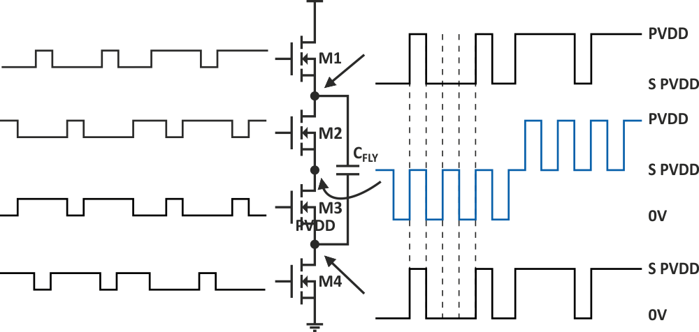
MERUS™ amplifier products create amplified output with a unique power stage topology that has four transistors or MOSFETs for each half-bridge power stage instead of the two seen in traditional amplifiers, as shown in Figure 4. The multilevel output stage offers great flexibility and allows for the configuration of the amplifier for optimal power performance in any application.
The half-bridge establishes multiple PWM output levels from a single supply. Each half-bridge uses four MOSFETs (shown as M1 through M4 in Figure 4), and each MOSFET is driven by an individual PWM signal. The capacitor (CFLY), which is “flying” between the top and bottom MOSFETs, is constantly charged by separate circuitry, thereby maintaining a fixed voltage potential. The “flying capacitor” therefore functions essentially as an extra supply rail. In this way, each half-bridge power stage establishes a three-level output signal at the output-switching node: 0 V, ½ PVDD and PVDD.
 |
||
| Figure 4. | Multilevel output stage. | |
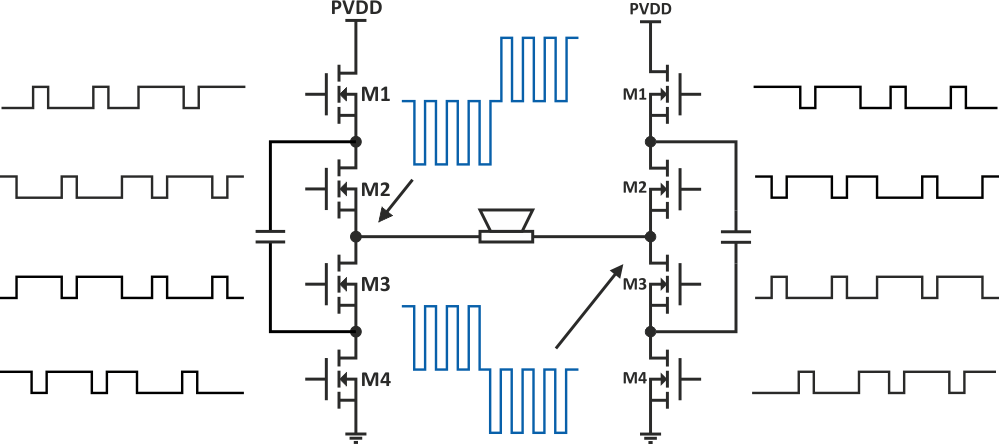
In a full bridge-tied load (BTL) configuration (see Figure 5), which is achieved by combining two three- level half-bridges with a switching pattern in which each half-bridge switching pattern is modulated with a 90° phase shift relative to the other, the resulting power stage can provide up to five levels of multilevel modulation patterns to a differentially connected speaker load.
 |
||
| Figure 5. | Multilevel full-bridge (BTL) output stage. | |
Since the resulting output frequency is higher and the individual voltage steps are smaller this approximates the output audio signal much closer to the input waveform than a conventional class D amplifiers.
A five-level system inherently quadruples the switching frequency at the output nodes, and the differentially connected speaker load also has much less out-of-band switching residuals. With high efficiency and better EMI and EMC management, the amplifier can thereby effectively be configured for filter-less operation.
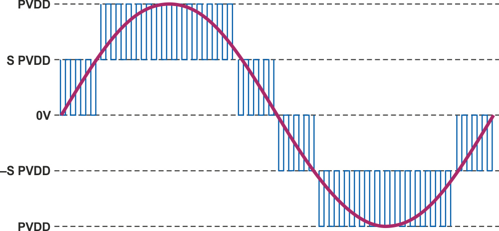
Figure 6 shows the resulting five-level differential output in a BTL configuration for one sinusoid cycle.
 |
||
| Figure 6. | Full bridge-tied load five-level output signal. | |
In this case, the speaker load switching frequency is four times the switching frequency of the MOSFETs at the half-bridge output nodes. Also note that the switching pattern gives rise to three states (as opposed to just one in a conventional class D amplifier) where complete cancellation of the out-of-band switching residue takes place, namely at –½ PVDD, 0 V and +½ PVDD. In these states the output of the two half-bridge outputs are either both 0 V or they both produce a perfectly ‘mirrored’ 50 percent duty cycle output.
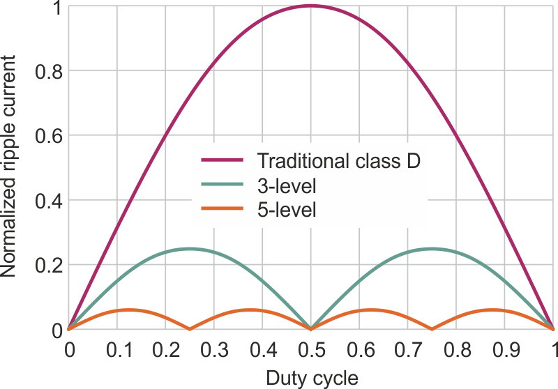
For the application, this translates directly to a reduction of the ripple current in the audio system output section. With no need to suppress out-of-band switching noise or artefacts, many applications do not require a common-mode applied LC filter.
 |
||
| Figure 7. | Multilevel amplifier zero states. | |
The effect of the reduced ripple current is shown in Figure 7. When normalized to the ripple current of a traditional class D amplifier (purple line), three-level or half-bridge (green line) and five-level or BTL (orange line) modulated output signals exhibit strongly reduced ripple currents. Also note the zero states for three- and five-level signals, points at which there is no ripple current. In addition to the inherently more efficient switching principle, overall dissipation and power loss are also significantly reduced due to the reduced ripple current in the external components.