This article describes the test results, and the modernization of several BPSs QW-MS605D, made in China, purchased by the author on eBay.com for one of his projects.
Michael Gurovich, USA
Recently, a large number of reasonably priced Lab BPSs that are made in China have appeared on the market. Such BPSs have become very popular among DIY folks simply because of their affordability.
The author purchased four such BPSs for his lab. Before starting to use them in the project, he opened one to see how it is built and test each one using a test load and an oscilloscope, to find out the actual output of these BPSs.
Knowing the popularity of these among DIY folks, the author decided to share his impressions, experiences and test results in this article.
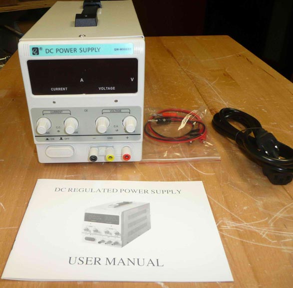
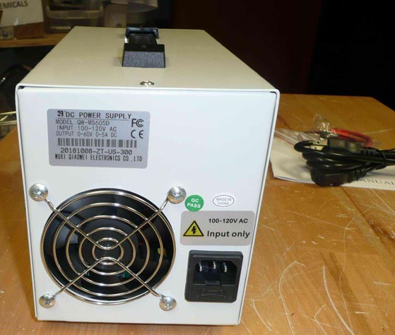
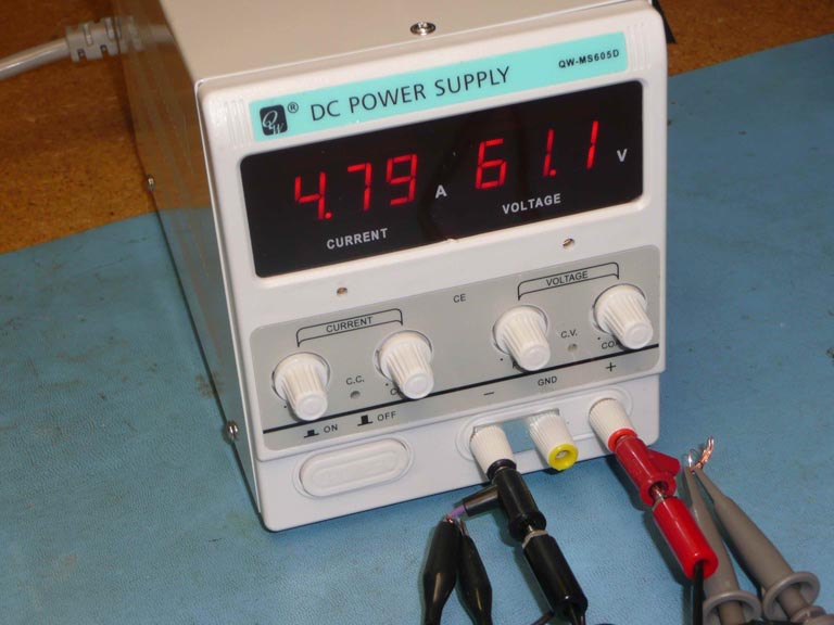
Let’s get started. The appearance of the BPS is shown in Figure 1 (front view), Figure 2 (rear view), Figure 3 (view of the turned on indicators).
 |
||
| Figure 1. | BPS’s front view. | |
 |
||
| Figure 2. | BPS’s Rear view. | |
 |
||
| Figure 3. | BPS’s indicators are ON. | |
The BPS looks good; it has separate digital indicators of the output current and voltage, a separate fine and coarse adjustment of the output voltage and the level of output current limitation. At the bottom of the front panel are the output terminals — positive, negative, and chassis. From the factory, the BPS comes with a negative terminal connected to the chassis (using a special jumper), but if necessary, you may connect a positive terminal to the chassis or leave both outputs floating (not grounded).
BPS dimensions are: width 125 mm, height 170 mm, depth (with the disconnected power cable) 280 mm. There is a carry handle on top. The weight of the device is just under 2 kg. For comparison, the author has in his laboratory an old linear Protek 3003B BPS with same output parameters and nearly-same dimensions, but with a weight of 6 kg.
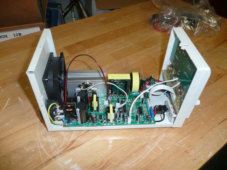
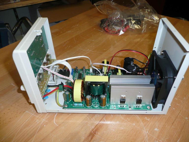
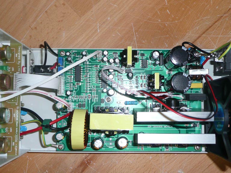
Now open the top cover and look inside. The first thing that was noticed was the low quality of the screws. The screw head is of poor quality and the screwdriver hardly rotates the screw. Looking ahead, I will say that the screws during assembly were replaced with better and more convenient to use. The view of the BPS with the top cover removed is shown in Figures 4,5,6.
 |
||
| Figure 4. | The view of the BPS with top cover removed on the left. | |
 |
||
| Figure 5. | The view of the BPS with top cover removed on the right. | |
 |
||
| Figure 6. | The top view of the BPS with top cover removed. | |
The design is quite standard – we have a chassis, the main board and the front panel board. On the rear chassis wall is a fan and a AC power cable connector with a built-in fuse.
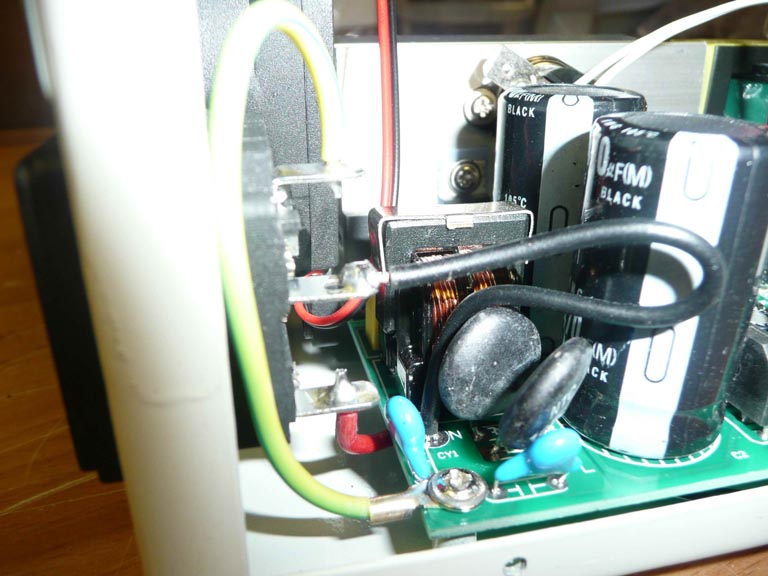
The next thing that worth to mention is the poor quality of soldering and preparation of the power wires going from the connector on the rear panel to the power switch on the front. During the removal of insulation from these wires, the copper core was damaged and soldering was performed without using flux. In addition, the insulation tube is not worn on the wires. This is shown in Figures 7 and 8. Once again, looking ahead, I will say that for the modification this BPS has been disassembled and these wires were unsoldered, and during assembly all the connections were restored using flux and insulated with heat shrink insulation.
 |
||
| Figure 7. | AC power connector wires. | |
 |
||
| Figure 8. | Power switch wires. | |
Figures 9 and 10 show the technical data of the BPS from the manufacturer - we will need them for comparison with our own measurement results. Particular attention should be paid to the last line in paragraph 2.2. The value of ripples and noise at the output is not more than 10 mV in voltage stabilization mode.
 |
||
| Figure 9. | BPS data declared by the manufacturer. | |
 |
||
| Figure 10. | BPS data declared by the manufacturer - continued. | |
Now, turn on the BPS and see what it provides to the output terminals.
For testing, the author used the following tools and equipment:
- Oscilloscope RIGOL DS-1054.
- Self-made Test Load with a resistance of 13 Ohm and a maximum power of 1200 W.
- DC Clamp Meter (DCCM) Hantek CC-65.
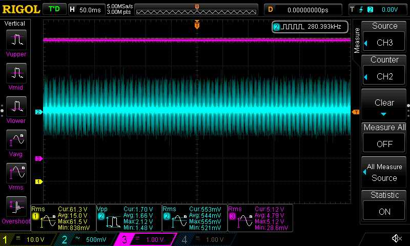
Explanation for all oscilloscope screenshots:
- Channel No. 1 - Yellow - shows the full output voltage of the BPS,
- Channel No. 2 - Blue - shows only the AC component of the output voltage,
- Channel No. 3 - Purple - shows the output of the DCCM with a scale of 1 V = 1 A.
At the bottom of the oscilloscope screen, the automatic measurement mode and the statistics of the results are turned on:
- Yellow channel - RMS (root mean square value).
- Blue channel - Vpp (peak to peak voltage value) and RMS,
- Purple channel - RMS.
The scale and gain of each channel are visible in the screenshots.
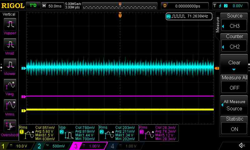
First, we test the output in IDLE mode (IDLE) -
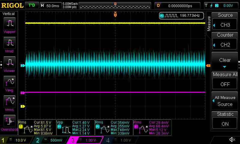
The output voltages are shown in Figure 11 (the output voltage regulator is set to minimum) and in Figure 12 (the output voltage regulator is set to maximum).
 |
||
| Figure 11. | Output voltage in IDLE mode. The output voltage control is set to minimum. | |
 |
||
| Figure 12. | Output voltage in IDLE mode. The output voltage control is set to maximum. | |
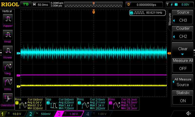
Now we connect the 13 Ohm load to the BPS output and repeat the measurements.
 |
||
| Figure 13. | Output voltage with connected load. The output voltage control is set to minimum. | |
 |
||
| Figure 14. | Output voltage with connected load. The output voltage control is set to maximum. | |
It can be seen that the level of high-frequency noise and ripple is huge and reaches 0.8 - 1.2 Vpp in the IDLE mode and becomes even higher under load and reaches 0.95 - 1.7 Vpp.
After some thinking and visual analysis of the main board, the author decided to replace several old components and add several new ones. The specs of all newly installed components are given at the end of the article.