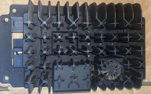
In this article, I want to talk about the experience of repairing a OEM Harman/Becker audio amplifier, which was installed in Mercedes-Benz cars. In this particular case, it was a 2005 Mercedes, installed OEM audio amplifier Harman/Becker 7019 (HS7019, Part # A1698201389, Figure 1).
 |
||
| Figure 1. | OEM Harman/Becker 7019 audio amplifier installed on Mercedes car(foto: Internet). | |
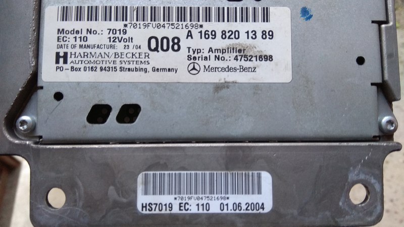
The factory markings on the amplifier block are shown in Figure 2.
 |
||
| Figure 2. | Mercedes Harman/Becker 7019 audio amplifier factory markings. | |
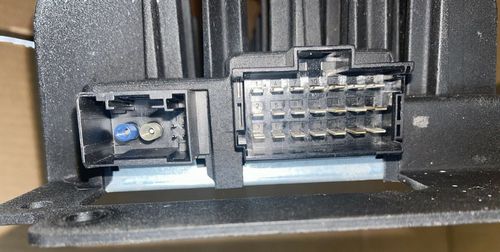
Note that the audio amplifier is included in the D2B fiber optic loopback bus, which is used for audio/communication/navigation. In other words, digital audio and some control signals are transmitted from the head unit (radio) to the amplifier via an optical line. The amplifier unit is installed in the car trunk behind the trim above the wheel arch. Figure 3 shows the connectors for connecting the amplifier: on the left is the D2B optical bus connector, on the right is a three-in-line connector for connecting power, control and acoustics outputs.
 |
||
| Figure 3. | Harman/Becker 7019 amplifier connectors. On the left you can see the connector for optical communication line (Pigtail). |
|
The obvious reasons for the amplifier unit malfunction have not been established, nevertheless, the car owner noticed that the amplifier malfunction began to appear periodically after the car had stood in the heat in the open sun for several days: when the head unit (radio, CD, Bluetooth) was turned on, the sound in speakers of the car was missing. If you turn off / on the head unit, then the sound appeared, and the amplifier could work stably for a long time. But over time, the amplifier malfunction began to appear more and more often. In some cases, disconnecting the battery, disconnecting the amplifier from the vehicle's on-board network helped. But in the future, all possible methods ceased to work and the amplifier did not start. At the same time, during all this time, no failure of the amplifier was observed in the active state.
Diagnostics of such standard units is difficult, and in many cases (as in this one) it is impossible due to the lack of specialized diagnostic devices, emulators, programmers, software and firmware. Nevertheless, the on-board systems of the car were diagnosed at the service center. All available diagnostic tools did not detect this amplifier block, but other blocks that were also connected to the optical communication line (for example, the navigation system block) were identified. This fact indicated that the optical communication line was working, and, probably, the problem was in the amplifier.
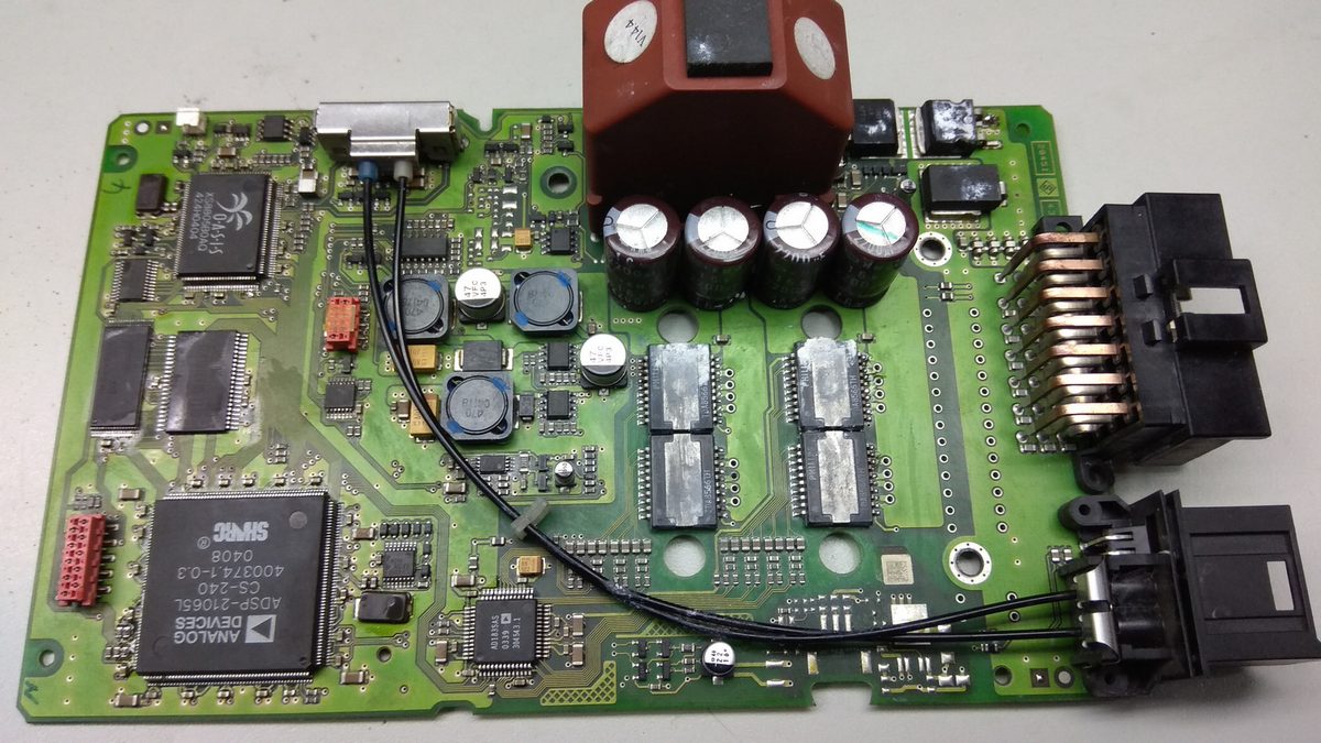
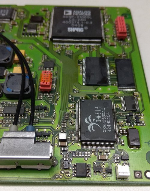
The amplifier block was opened. The Harman / Becker 7019 amplifier board is shown in Figure 4. High resolution images of the amplifier board are available in the download section.
 |
||
| Figure 4. | Mercedes Harman/Becker 7019 audio amplifier PCB. | |
Before the amplifier came to me, someone tried to repair it: there were traces of soldering of power MOSFETs, power amplifier IC’s on the board, there was no thermal paste on these elements. Removal or replacement of elements was not performed.
A quick inspection of the board revealed no signs of overheating or damage to any elements.
The amplifier includes: OASIS XS8805BOAQ processor, Analog Devices ADSP-21065L 32-bit digital signal processor (DSP), AD1835AS 24-bit codec (ADC + DAC), four Philips TDA8566TH power amplifier chips, STMicroelectronics M29W040B90N6 flash memory chip, RAM Samsung K6R1016V1D. There is space for a small cooling fan (next to the OASIS processor) in the amplifier case (in the top cover), but it is not installed. To cool the OASIS processor, an amplifier case is used (through a thermal pad).
Initial diagnostics was carried out by connecting the amplifier board (without housing) to the vehicle's on-board system. After turning on the head unit (radio), a glow was noticeable in the optical line connectors and a slight heating of the OASIS processor. The main supply voltages (3.3 V) of the processor, DSP, codec, Flash memory and RAM are normal. There was no power supply (+12 V) on the power amplifier chips.
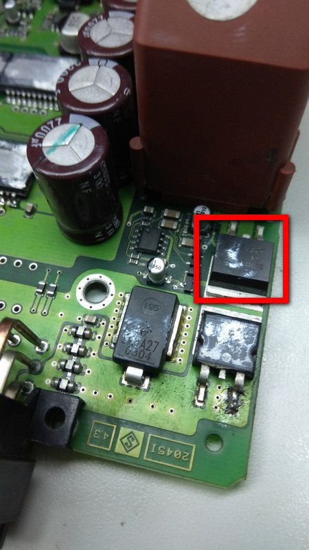
Power control of the power amplifier IC’s is carried out by the OASIS processor through the power MOSFET (Figure 5) through some matching and protection circuits. There were no control signals at the gate of the transistor. The forced supply of power to the power amplifier IC’s (bypassing the MOSFET) also did not give any results.
 |
||
| Figure 5. | Harman/Becker 7019 amplifier PCB. MOSFET to control power supply for TDA8566 IC’s. |
|
Further, when examining the board under a microscope, it was revealed:
- Some DSP pins have a gray coating. Between the pins of the DSP there was a loose consistency, similar to oxide (or the factory welding flux began to look like this), mainly on the side that is closer to the edge of the board.
- Small oxides on the TDA8566 IC’s pins.
- Gray coating on some pins of the OASIS processor. Oxidation between some pins.
- Revealed the destruction of the soldering of the OASIS processor leads, the lack of reliable contact of the leads with the PCB.
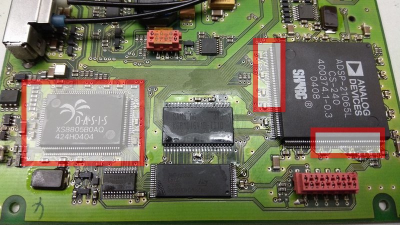
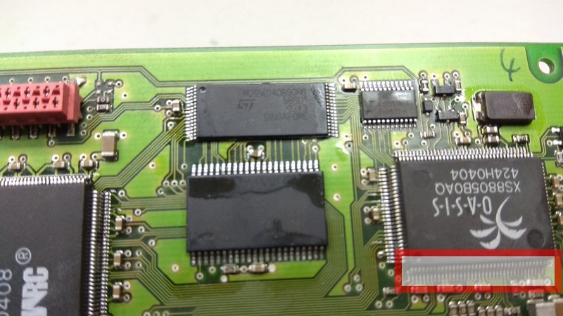
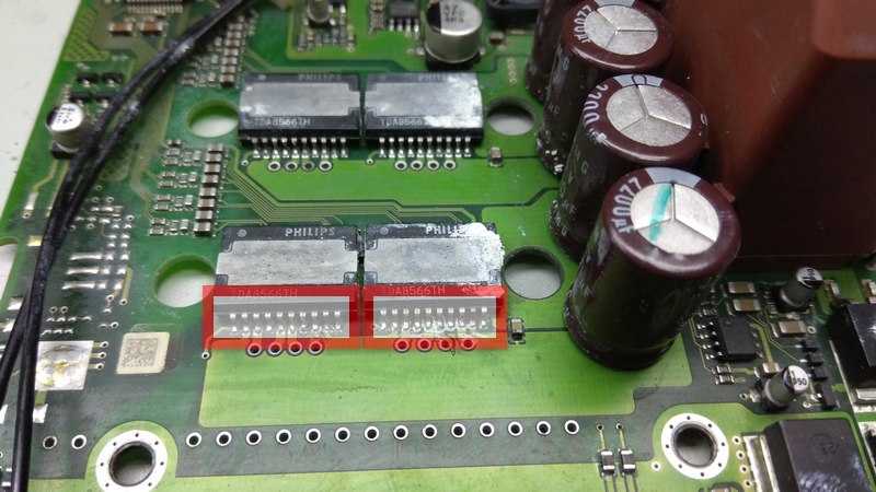
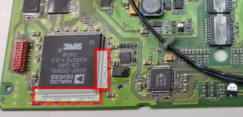
Figures 6 and 7 highlight the identified problem areas and elements on the Harman/Becker 7019 amplifier board.
 |
||
 |
||
 |
||
| Figure 6. | Harman/Becker 7019 audio amplifier PCB. Revealed the soldering destruction of the OASIS processor leads. |
|
 |
||
 |
||
| Figure 7. | Harman/Becker 7019 audio amplifier PCB. Some DSP pins have a gray coating, Small oxides on the TDA8566 IC’s pins. |
|
Taking into account that the amplifier unit has a nonpressurized body and, in my opinion, not a very good location, we can draw some conclusions:
- Moisture has somehow got into the amplifier unit (possibly condensation)
- Over time heat dissipation from the OASIS processor deteriorates, additional heating leads to the destruction of the soldering of the processor pins to the printed circuit board and, accordingly, the formation of an oxide film in the places of soldering destruction.
To eliminate the observed defects, first the amplifier board and the element leads were thoroughly cleaned of oxidation and contamination. To solder all the elements I used a bottom heating table, a soldering station heater and high-quality flux. The temperature of the bottom heating was set at 350 °С, the temperature of heater was also 350 °С. After warming up the board and elements each processor pin was additionally soldered with a soldering iron (under a microscope).
After the board cooled down, I checked all the elements again, the reliability of the contact of the processor pins with the PCB contact pads was restored, oxides and contamination were not observed.
The amplifier was assembled, thermal paste was applied to the MOSFET’s and power amplifier IC’s, the thermal pad on the OASIS processor was replaced. After connecting the amplifier to the on-board network of the car and turning on the head unit, the sound in the speakers and the subwoofer appeared, no distortions or interruptions in operation were detected. Two weeks of testing the amplifier in the car also showed no problems.