Many pc-board assemblies require shields to reduce susceptibility to interference from electromagnetic fields. A classic example is a radio receiver, in which the front end usually needs high isolation from the tuning synthesizer. Historically, shields for low-volume or low-cost applications involve trade-offs. You can't justify the cost of a custom-cast shield, and shields machined from aluminum burn through money as fast as the end mills go dull. You can make a simple shield for just a few dollars by using commonly available die-cast aluminum “project boxes,” such as those from Hammond Manufacturing. These boxes come in sizes from 2×2 in. to more than 7×4 in. You turn the project box into a shield by sandwiching the pc board between the top and the bottom of the box, thus completely enclosing the sensitive circuitry.
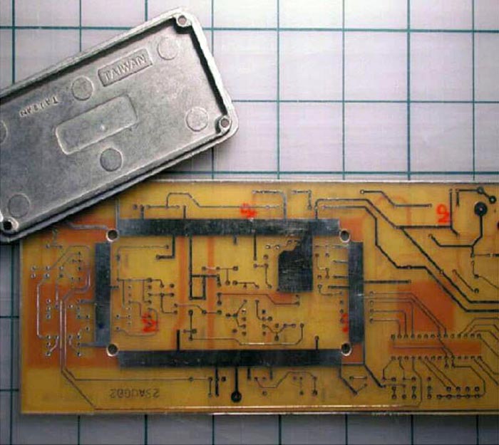
The basic idea is to choose a box that is big enough to fit the sensitive circuitry that you want to shield. Then, lay out the circuit in such a way that you can sandwich the board between the cover and the body of the project box. To have a continuous ground around the lip of the box, place a 1/8- to 1/4-in.-wide ground track all the way around the area where the box will sit on the top and the bottom sides of the board. Then, add mounting holes in the corner so that you can assemble the box around the pc board and screw it together (Figure 1). To get signals into and out of the shield on a multilayer board is easy: Just use the inner layers and go under the ground track. On a double-sided board, you can break the track for traces, or – better yet – you can use a 0.25 W resistor to bridge the track. The 0.25 W-resistor method serves two purposes. First, it allows a signal to get over the ground track without cutting it. Second, it is a perfect place to add impedance to the signal line and hence obtain high-frequency filtering. This method can help to prevent stray signals from getting into the sensitive circuitry you are trying to protect.
 |
||
| Figure 1. | You should place a ground track on the top and the bottom of the pc board where the project-box shield sits. |
|
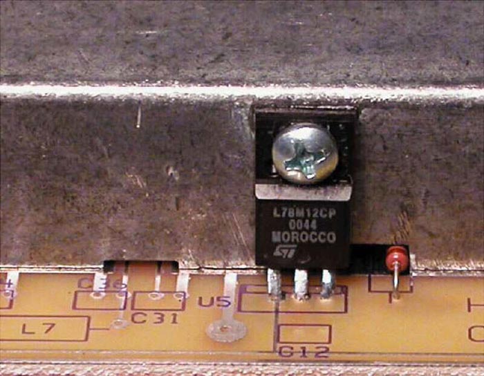
For both the methods mentioned, you need to notch the box's body with a mill or file (Figure 2) to provide clearance to the resistor or traces. Note, however, that this notch acts as a waveguide for RF signals, so keep the following in mind: The longest dimension of any gap should be much less than one-quarter of a wavelength at the highest frequency of interest. In high-performance shielding work, strive to keep the gaps below one-twentieth of a wavelength. If you want to “fill up” the gap, you can buy conductive foam or metal gaskets from 3M and WL Gore; you can use these gaskets to fill in any gap to make it electrically smaller. Likewise, any gaps in the box-to-pc-board contact as it sits on the ground track also act as waveguides. Depending on the required frequency of operation, these gaps may or may not cause a loss of shielding effectiveness (Reference 1). As a side benefit, you can also use the shield as a heat sink. By placing TO-220 regulators outside the box, you can attach the regulators' heat sink to the enclosure. Thus, you have not only a shield, but also a heat sink (Figure 2).
 |
||
| Figure 2. | You can mill small notches in the shield to provide signal access. As a side benefit, you can use the shield as a heat sink for TO-220 regulators. |
|
Reference
- Ott, Henry, Noise-reduction techniques in electronic systems, Wiley-Interscience, 1988, ISBN 0-471-85068-3.