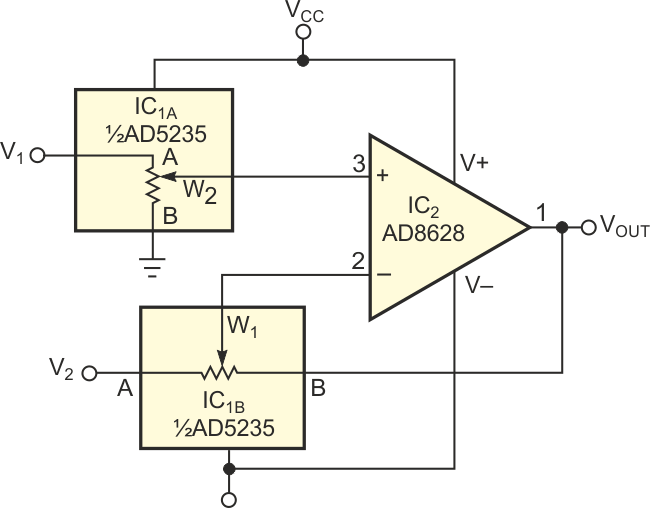
You sometimes need to measure a small signal in the presence of a large common-mode signal. Traditional instrumentation amplifiers that use two or three op amps in their internal structure find common use in these applications. The circuit in Figure 1 presents an alternative approach that is useful when low cost and low drift are important, but when you don't need high precision.
 |
||
| Figure 1. | A low-cost difference amplifier uses digital potentiometers to set the gain. | |
The circuit uses IC1, a dual 1024-position AD5235 digital potentiometer with nonvolatile memory. It also uses IC2, an AD8628 autozero amplifier to form a difference amplifier with a gain of 15. The programming capability of the AD5235 allows you to perform gain setting and trimming in a single step. Autozero amplifiers, such as the AD8628 and the AD855x family, are the best choices in these types of applications. They have high dc accuracy and add negligible errors to the output. The long-term stability of the autozero amplifiers eliminates the need for repeated calibration. With a minimum common-mode rejection ratio of 140 dB for the autozero amplifier, the resistor match is the limiting factor in most circuits. The transfer function of the circuit in Figure 1 is:
 |
(1) |
where
RAnBn = nominal end-to-end resistance;
RWnBn = terminal resistance, W to B: RWB = RAB × D/2N;
RWnAn = terminal resistance, W to A: RWA = RAB – RWB = RAB (1 – D/2N);
D= decimal equivalent of the binary word;
N = number of bits.
A special situation arises when

The transfer-function equation reduces to
 |
(2) |
You can see that the output is the difference of the two inputs times a gain factor that you can set to any desired gain, including unity. Equation 2 holds true because the same chip integrates all the resistors; therefore, their values match tightly. The low-frequency common-mode rejection ratio is approximately 98 dB (Figure 2). Because of the tight matching, the circuit can achieve a temperature coefficient of 15 ppm/°C. Although the circuit has lower performance than precision instrumentation amplifiers, it is adequate for many low-cost applications.
 |
||
| Figure 2. | A plot for common-mode rejection ratio versus frequency for the circuit in Figure 1 yields a figure of 98 dB. |
|