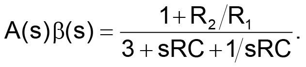
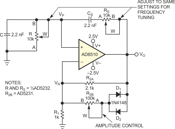
Digital potentiometers are versatile devices; you can use them in many filtering and waveform-generation applications. This Design Idea describes an oscillator in which setting the resistance of two digital potentiometers independently programs the oscillation amplitude and frequency. Figure 1 shows a typical diode-stabilized Wien-bridge oscillator that generates accurate sine waves from 10 to 200 kHz. In this classic oscillator circuit, the Wien network comprising R, RS, C, and CS, provides positive feedback, and R1 and R2 provide negative feedback. R2 is the parallel combination of R2A and R2B in series with RDIODE. To establish sustainable oscillation, the phase shift of the loop should be 0° when the loop gain is unity. In this circuit, you can determine the loop gain, A(jω)β(jω) by multiplying the amplifier gain by the transfer function VP/VO. With R = RS and C = CS, the loop gain is
 |
(1) |
Substituting s = jω and rearranging the real and imaginary terms yields
(2)
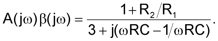 |
(2) |
You define the phase angle of the loop gain as
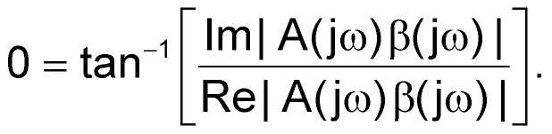 |
(3) |
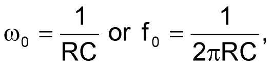
You force the imaginary term to zero to set the phase shift to 0°. As a result, the oscillation frequency becomes
 |
(4) |
where R is the programmable resistance:
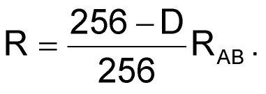 |
(5) |
D is the decimal equivalent of the digital code programmed in the AD5232, and RAB is its end-to-end resistance. To sustain oscillation, the bridge must be in balance. If the positive feedback is too great, the oscillation amplitude increases until the amplifier saturates. If the negative feedback is too great, the oscillation amplitude damps out. As Equation 2 shows, the attenuation of the loop is 3 at resonance. Thus, setting R2/R1 = 2 balances the bridge. In practice, you should set R2/R1 slightly higher than 2 to ensure that the oscillation can start. The alternating turn-on of the diodes makes R2/R1 momentarily smaller than 2, thereby stabilizing the oscillation. In addition, R2B can independently tune the amplitude, because 2/3(VO) = ID R2B + VD.
 |
||
| Figure 1. | This Wien-bridge oscillator uses digital potentiometers to provide independent settings of amplitude and frequency. |
|
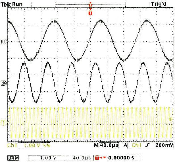
You can short-circuit R2B, which yields an oscillation amplitude of approximately ±0.6 V. VO, ID, and VD are interdependent variables. With proper selection of R2B, the circuit can reach equilibrium such that VO converges. However, R2B should not be large enough to saturate the output. In this circuit, R2B is a separate 100-kΩ digital potentiometer. As the resistance varies from the minimum value to 35 kΩ, the oscillation amplitude varies from ±0.6 to ±2.3 V. Using 2.2 nF for C and CS, and a 10-kΩ dual digital potentiometer with R and RS set to 8, 4, and 0.7 kΩ, you can tune the oscillation frequency to 8.8, 17.6, and 100 kHz, respectively (Figure 2). The frequency error is ±3%. Higher frequencies are achievable with increased error; at 200 kHz, the error becomes ±6%.
 |
||
| Figure 2. | These three frequencies reflect three digital-potentiometer settings. | |
Two cautionary notes are in order: In frequency-dependent applications, you should be aware that the bandwidth of the digital potentiometer is a function of the programmed resistance. You must therefore take care not to violate the bandwidth limitations. In addition, the frequency tuning requires that you adjust R and RS to the same setting. If you adjust the two channels one at a time, an unacceptable intermediate state may occur. If this problem is an issue, you can use separate devices in daisy-chain mode, enabling you to simultaneously program the parts to the same setting.