Machine vision systems use very short flashes of intense light to produce high speed images used in a wide variety of data processing applications. For instance, fast moving conveyor belts are run through machine vision systems for quick label and defect inspections. IR and laser LED flashes are commonly used for proximity and motion-sensing machine vision. Security systems send out high speed, hard-to-detect LED flashes to sense motion and capture and store security footage.
One challenge in all of these systems is creating the very high current and short-term (microseconds) LED camera flash waveforms, which can be spread out over long periods of time, such as 100 ms to over 1 s. Creating short, square LED flash waveforms separated by long periods of time is nontrivial. As the drive currents for the LEDs (or strings of LEDs) rise above 1 A and the LED on-times shrink to microseconds, the challenge increases. Many LED drivers with high speed PWM capabilities may not efficiently handle long off-times and high currents for short amounts of time without degradation of the square-type waveform needed for proper high speed image processing.
Proprietary LED Flash
Fortunately, the LT3932 high speed LED driver can provide machine vision camera flash for up to 2 A LED strings, even with long off-times of 1 second, 1 hour, 1 day, or longer (Figure 1). The LT3932’s special camera flash feature allows it to maintain the output capacitor and control loop charge state, even during long off-times. After sampling the state of the output and control loop capacitors, the LT3932 continues to trickle-charge these components during long off-times to compensate for typical leakage currents, which is not accounted for by other LED drivers.
 |
|
| Figure 1 | An example of machine vision on an industrial conveyor belt. Inspection systems move at many different speeds, yet the flash technology must be fast and crisp. |
The proprietary flash technology of the LT3932 scales up when drivers are paralleled for increased LED flash current. The desired flash shape and integrity are maintained. Figure 2 shows how easy it is to parallel two drivers for a 3 A camera flash – designs up to 4 A are possible.
 |
|
| Figure 2 | Parallel LT3932 1.5 A LED drivers yield 3 A machine vision LED pulses with long off-times relative to standard PWM dimming frequencies. |
LED flash requirements for machine vision systems are far more demanding than a standard PWM dimming driver can meet. That is, most high end LED drivers are designed to produce PWM dimming brightness control at a PWM frequency of at least 100 Hz. This is because lower frequencies can be perceived by the human eye as an annoying flicker or strobing, even if the LED waveforms are square and repeatable. At 100 Hz, the theoretical maximum off-time is about 10 ms. During the 10 ms off-time, if designed correctly, an LED driver loses minimal output capacitor charge, allowing it to start its control loop in the approximately the same state in which it ended the last PWM ON pulse. A quick response and ramp-up of the inductor current and the next LED PWM ON pulse can be quick and repeatable, with minimized start-up time. Longer off-times (for frequencies below 100 Hz) risk output capacitor charge loss due to leakage, preventing a quick response when the LED is turned back on.
Parallel LED Drivers for Higher Current
LED drivers act as current sources, regulating the current sent out through the light emitting diodes. Since current only flows in a single direction to the output, multiple LED drivers can be placed in parallel and their currents sum through the load. Current sources do not need to be protected against current running backward through one converter or having mismatched outputs. Voltage regulators, on the other hand, are not inherently good at current sharing. If they are all trying to regulate the output voltage to a single point, and there are slight differences in their feedback networks, a regulator may draw reverse current.
An LED driver maintains its output current, regardless of other drivers that may supply additional current summed at the output load. This makes paralleling LED drivers quite simple. For example, the LED flash system of two parallel LT3932 LED drivers shown in Figure 1 efficiently drives 4 LEDs at 3 A with short 10 µs pulses spread out by long periods of time – defined by the machine vision system. Each LT3932 converter sources half of the total string current during PWM on-time and turns off and saves its output state during PWM off-times. The off-time can be short or long, with no effect on the flash waveform repeatability.
 |
|
| Figure 3 | 3 A camera flash waveform of Figure 1’s parallel LED drivers looks the same regardless of the amount of PWM off-time. Waveforms show that a 10 µs pulse after (a) 10 ms and after (b) one second are the same. The LT3932 LED flash also looks the same after a day or longer of PWM off-time. |
Parallel camera flash applications share nearly the same simplicity as single converters during long off-times. The converters observe the shared output voltage at the end of the last PWM on pulse, and keep the output capacitor charged to that state, even during long off-times. Each converter disconnects its PWM from the shared load and keeps its output capacitor charged to approximately the last voltage state by sourcing current to that capacitor as it leaks energy. Any leakage experienced by these capacitors over long off-times is overcome by the small amount of maintenance current. When the next PWM on pulse starts, the PWM MOSFETs of each converter are turned on and the output capacitors start up in approximately same state as the last pulse, regardless of whether 10 ms has passed or a full day.
Figures 3(a) and 3(b) demonstrate the LT3932 parallel LED drivers driving 4 LEDs at 3 A with a 10 µs machine vision camera pulse. The LED pulse is sharp and fast, regardless of whether there is a 10 ms PWM off-time (100 Hz) or a 1 s PWM off-time (1 Hz), which is ideal for machine vision systems.
Even Higher Current Is Possible
Parallel LED drivers are not limited to two converters. Three or more converters can be paralleled to create even higher current waveforms with sharp edges. Since this system does not have a master or slave device, all of the converters source the same amount of current and share the load equally. It is recommended that all of the parallel LED driver converters share the same synchronized clock and remain in-phase. This ensures that all converters have approximately the same phasing on the ripple of their output capacitors so that ripple currents do not flow backward or between the different converters. It is important for the PWM pulse waveform to remain in-phase with the 2 MHz synchronization clock. This ensures that the LED flash waveform remains square and without jitter, producing the best image processing results.
 |
|
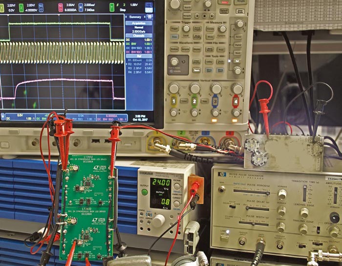
| Figure 4 | Two DC2286A LT3932 demo circuits are easily connected in parallel to create the 3 A to 4 A machine vision LED flash application shown in Figure 1. |
The LT3932 demonstration circuit (DC2286A) is designed to drive 1 A of LED current through one or two LEDs as a step-down LED driver. It can easily be altered and paralleled, as shown in Figure 1, for higher current, higher voltage, or parallel operation. Figure 4 demonstrates how two of these circuits are easily connected together to drive 10 µs, 3 A pulses through 4 LEDs from 24 V input. For testing purposes, a pulse generator can be used for the synchronized clock signal, as shown in Figure 4. In a production machine vision system, a clock chip can be used to generate the synchronized sync and PWM pulses. For higher current pulses, add more demonstration circuit DC2286A converters using the same parallel scheme.
Conclusion
Machine vision systems can use parallel LED drivers to create the fast, square, high current waveforms required for automated image processing. The LT3932 LED driver’s proprietary camera flash technology can be extended to higher currents by connecting parallel converters. 3 A and higher pulses on the order of microseconds are possible with parallel LT3932 converters, even with long off-times. LED camera flash waveforms remain square and without jitter, no matter how long the off-time between LED flashes may be.