A switched-mode power supply (SMPS) employing peak current-mode control (PCMC) requires a ramp signal to slope-compensate the inner (current) control loop. Slope compensation stabilizes the current loop, which would otherwise exhibit subharmonic oscillation when operating in continuous conduction mode with a duty factor near or above 50%. Also, the current that should be controlled is the average value of inductor current, which is directly related to load current since the output capacitor must have zero average current.
Using peak current-mode control, or PCMC, the difference between peak and average values of inductor current is an error that should be corrected. Slope compensation corrects this peak-to-average inductor current error.
Slope compensation is implemented by summing a periodic ramp with the sensed current signal. One way to create the ramp is to use the R-C oscillator waveform generated by the control IC.[1, 2] The oscillator is generally buffered by an emitter follower and fed into a resistor, summing the oscillator ramp with the sensed current signal, which feeds another resistor. The sum is sent to the control IC’s sensed current pin, ISNS.
This technique loads the oscillator and introduces noise, though, which can falsely trigger the pulse-width modulation (PWM) control. Recent application notes from PCMC IC makers suggest against loading the oscillator, even with an emitter follower buffer.[3, 4]
The recommended way to obtain the ramp is to integrate the MOSFET’s gate-drive output with an R-C network. The gate-drive output is a rectangular pulse of 0 to about 10 V in amplitude. Proper selection of R and C values integrates this pulse and produces a ramp waveform. When the pulse goes low, a diode discharges the capacitor, and the ramp returns to near zero.
This method is quite effective, but a problem occurs if the SMPS input voltage varies considerably. If the input ranges from 9 to 16 V, and the control IC is driven directly from this varying input, the slope of the compensating ramp will vary directly with the input voltage. This results in overcompensation and actually increases peak-to-average error.
The circuit in Figure 1, however, generates a ramp whose slope is independent of the input voltage. It does so by charging a capacitor with a constant-current source using the control IC’s (U1’s) PWM gate drive (pin 6, OUT) as an input.
 |
|
| Figure 1. | Adding a simple constant-current-source, gate-driven ramp generator for slope compensation improves the stability and accuracy of a switch- mode power supply. |
Suppose that the input voltage to the SMPS (pin 7 on U1, whose connection has been omitted for clarity), is at the 9-V minimum. When the pulse is high, at around 7.5 to 8.0 V, the network R1-Q1-Q2-R2 forms a constant-current source that feeds capacitor C1. For R1 = 220 Ω (and VBE = 0.65 V), the current is about 2.95 mA. When fed into C1 for a time t, this constant current produces a ramp voltage across C1 in accordance with the equation:
or
and the slope of the ramp is:
So for the example circuit, the slope is

For a switching period of 3.0 µs (333 kHz) and a duty factor of 2/3, the on-time of the PWM pulse is 2.0 µs. Therefore, the slope-compensating ramp’s peak is 3.94 V.
When the pulse goes low, diode D1 conducts and discharges C1 to near 0 V. R1 and C1 must be chosen so the ramp’s peak voltage doesn’t equal or exceed the minimum input voltage, which is 9.0 V in this case. Also, R3 and C1 must be chosen so R3 doesn’t load down C1.
 |
|
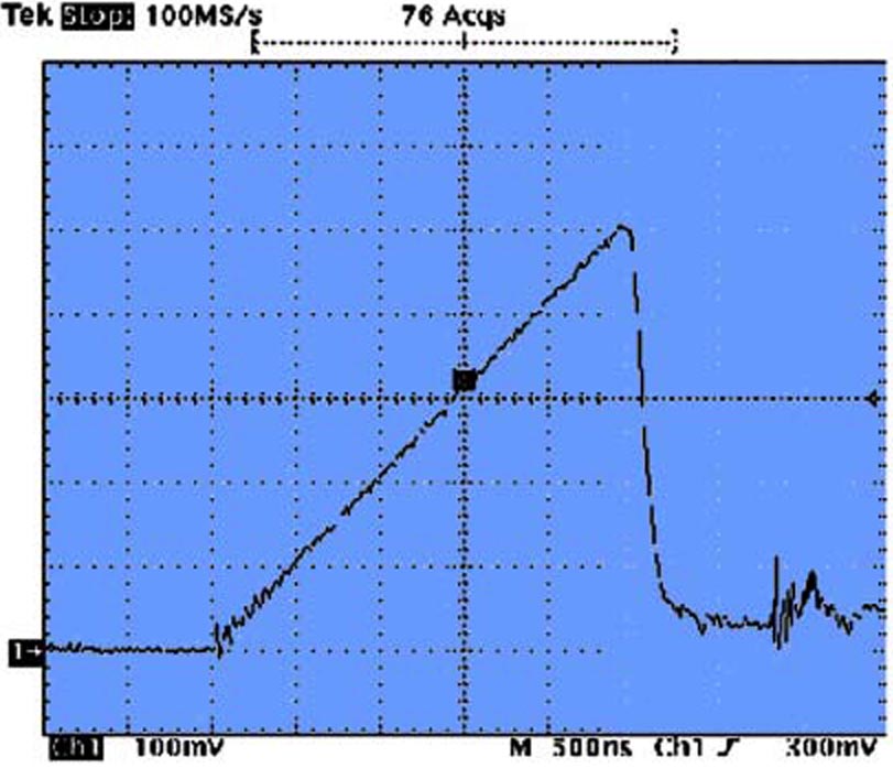
| Figure 2. | A measurement of the ramp generated by the circuit in Figure 1 showed no change as the input was varied from 9 to 16 V. |
When the input is at its maximum, 16.0 V, the ramp slope is still 1.97 V/µs, which would not be the case when using an R-C network. The ramp is inputted to resistor R3, and the sensed current waveform, ISNS_UNFLTRD, is inputted to R4. The sum of the two appears at U1 pin 3, which is the control IC’s current-sense input. The measured waveform showed no change when varying the input from 9 to 16 V (Fig. 2).
References:
- The UCC38C42 Family Of High-Speed, BiCMOS Current Mode PWM Controllers – Application Note; Bill Andreycak, Texas Instruments, SLUA-257, Feb. 2002
- Practical Considerations In Current-Mode Power Supplies; Bill Andreycak, Texas Instruments, 2001
- Ramp Compensation for the NCP1200, AND8029/D; Christophe Basso, On Semiconductor, March 2001, Rev. 1
- Single CS3842A Provides Control for 500-W/200-kHz Current-Mode Power Supply; CS3842AN/D, On Semiconductor, April 2001, Rev. 1