Permanent magnet DC (PMDC) motors offer smaller solution size and increased efficiency in applications such as portable vacuums and cordless electric power tools. When designing an isolated power supply for PMDC motors, there are several considerations to keep in mind – transient response, required peak load, solution size and cost – that directly influence the design of the power architecture and the chosen power-converter topologies.
One particular challenge associated with PMDC motors is that the motor’s peak current can be several times larger than its steady-state current. This peak load directly affects the power topology selection and cost of the isolated power supply. To illustrate this characteristic of PMDCs, consider the basic operational voltage equation for a DC motor (Equation 1):
 |
(1) |
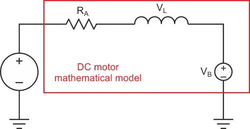
Here, VS is the applied motor-supply voltage, VB is the back electromotive force (EMF) of the motor, VL is the voltage across the rotor inductance, and IA and RA are the armature current and resistance, respectively. This operational voltage relationship is illustrated in Figure 1.
 |
|
| Figure 1. | Simplified model of a DC motor illustrates the PMDC characteristics. |
When the motor is completely stationary, the back EMF is equal to 0 V – given the absence of any rotary motion – and the current demanded by the motor is only limited by the armature resistance. Because the armature resistance is typically <1 Ω, the initial current demand of the motor can be several times higher than the steady-state current when applying the full, nominal supply voltage before a back EMF has developed.
Approaches for addressing peak current stress
The large initial current demand presents a particular challenge to an isolated power supply, and that requires careful consideration to determine which trade-offs are acceptable for the end product. Your choices include:
Designing the isolated converter to handle the peak power during startup
This approach may be acceptable if the peak motor current is similar in value to the maximum steady-state motor current. It can become expensive, however, if the peak load is several times larger, as you must design both the power factor correction (PFC) and isolated DC/DC power stages for the higher peak load. This approach requires more expensive elements in the power stages – even necessitating a change in the required power-converter topology – and may also increase the overall size and weight of the power supply if you need larger magnetics to avoid saturation.
Using a large capacitor bank
In this approach, the isolated power supply builds up significant charge in a capacitor bank connected to the output of the power supply while the motor is not enabled. Once the motor is enabled, the stored charge supplies the peak load commanded by the motor while allowing for some acceptable droop in the output voltage. This approach is simple but requires the ability to disconnect the motor from the power supply so that the isolated power supply can start up without the motor load connected. Using a large capacitor bank is also not a good idea for higher-power PMDCs, as the required capacitor bank size becomes unreasonably large.
Output constant-current limiting
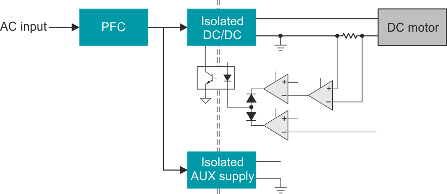
If you build output current limiting into the isolated power-supply feedback loop, the power supply is capable of regulating the maximum output current. This approach enables a lower peak-power design requirement for the power supply and avoids the need for a large capacitor bank. But the output current regulation circuitry does require a separate bias supply in order to properly regulate the output current during startup, which translates into a separate isolated auxiliary supply in addition to current-sensing circuitry, as shown in Figure 2.
 |
|
| Figure 2. | The AC/DC supply block diagram highlights constant-current and constant-voltage regulation loops. |
Reducing peak current stress through duty-cycle limitation
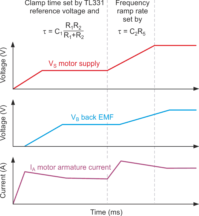
If the initial speed and startup time of the motor are not time-critical and a longer startup time is acceptable in the application, another approach is to clamp the output voltage of the isolated DC/DC converter during startup for a period of time longer than the electrical time constant of the motor. With fixed-frequency controllers, you can clamp the maximum duty cycle. In variable-frequency converters such as inductor-inductor-capacitor (LLC) resonant converters, you can clamp the minimum switching frequency.
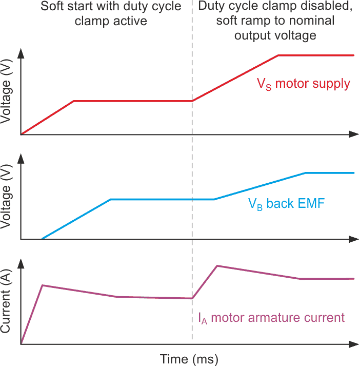
Using a clamp enables a small initial voltage to develop on the output of the isolated DC/DC converter for a long enough period of time to allow the motor to turn slowly and begin to develop a back EMF, as shown in Figure 3. Because the initial supply voltage is small, the motor’s current demand is limited to a value much closer to its steady-state value. After a back EMF has developed and the motor current has reached a steady state, the output voltage of the isolated DC/DC can safely ramp up to the nominal output voltage while avoiding excess current stress within the converter.
 |
|
| Figure 3. | Startup with a duty-cycle clamp enables a small initial voltage. |
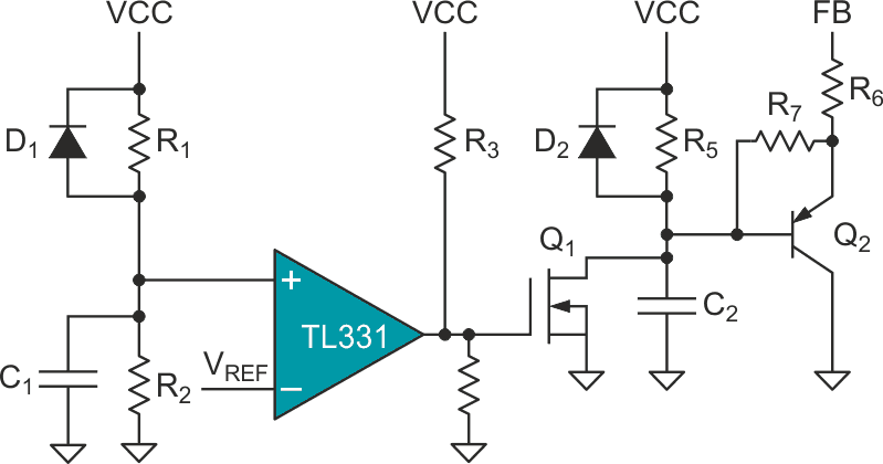
Locating the clamp circuit on the primary side of the isolated DC/DC converter eliminates the need for separate auxiliary supply. Figure 4 shows an example implementation using a general-purpose comparator and a couple of small-signal transistors. This particular example pairs the clamp circuit with the UCC256402 controller, which has a fixed FB pin voltage of 5.6 V to act as a minimum frequency clamp for a half-bridge LLC resonant converter.
 |
|
| Figure 4. | Primary-side clamp circuit uses a general-purpose comparator and a couple of small-signal transistors. |
In the initial state of the clamp, both Q1 and Q2 are on, with an initial voltage of 0 V on both C1 and C2. Because Q1 pulls the base of Q2 down to ground, a current proportional to
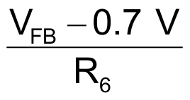
is sunk out of the FB pin of the isolated DC/DC controller. In the case of UCC256402 controller, this current sink keeps the VCR gate turn-off thresholds limited to
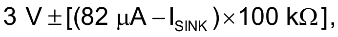
providing the frequency clamping function. The amount of time during which the clamp is active is set by the RC time constant formed by C1, R1 and R2 and when the voltage on C1 becomes larger than the reference voltage of the TL331 comparator, as shown in Figure 5.
 |
|
| Figure 5. | Clamp circuit states are shown vs. output voltage rise. |
As the TL331 is an open-collector comparator, it pulls the gate of Q1 down to ground, turning Q1 off. As the voltage on C2 begins to charge up through R5, the amount of current pulled out of the FB pin slowly decreases, giving a soft, gradual release of the frequency clamp circuit. D1 and D2 serve as a quick reset of the clamp circuit to quickly discharge C1 and C2 if bias is removed from the primary-side circuitry, such as in the event of fault protection.
Peak current comparison
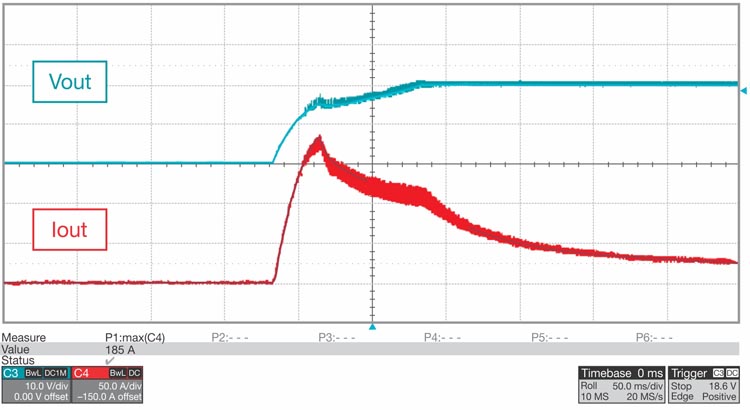
The above circuit enabled a 500-W continuous-conduction-mode (CCM) PFC boost converter plus isolated half-bridge LLC converter reference design to successfully start up and power a shop vacuum. The waveforms shown in Figure 6 illustrate the output voltage (10 V/div) of the power supply and the current demand (50 A/div) of the motor without frequency clamping. The peak armature current of the motor is 186 A. Significant current stress is present for 200 ms before settling to a steady-state current of 25 A in 300 ms after the motor begins turning.
 |
|
| Figure 6. | The waveforms show motor-supply voltage and current without frequency clamping. |
The waveforms in Figure 7 illustrate the output voltage (10 V/div) of the power supply and the current demand (10 A/div) of the motor with frequency clamping enabled during startup. The peak current is just above 35 A, much closer to the motor’s 25-A nominal rating.
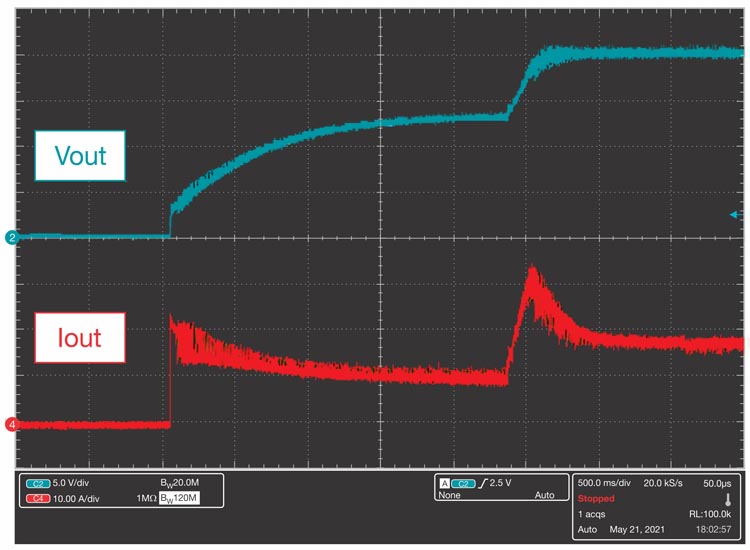 |
|
| Figure 7. | The waveforms show motor-supply voltage and current with frequency clamping. |
The motor current reaches steady state in 3 seconds after the motor begins turning.
The inclusion of a simple clamp circuit satisfies the goal of starting up a DC motor while avoiding high current stress within an AC/DC supply, and provides considerable bill-of-materials (BOM) savings compared to other approaches. This approach can be paired with non-LLC topologies as well to act as a duty-cycle clamp by tying into the COMP pin of the PWM controller. Designing an AC/DC supply to support the full peak load commanded by the motor would require being able to supply more than five times the steady state motor current.
This significant power level and current stress would require a much more expensive topology for both PFC and isolated DC/DC – such as an interleaved CCM PFC and phase-shifted full bridge – that adds significant BOM cost. A clamp circuit also has BOM cost savings compared to output constant-current limiting by avoiding the need for a separate isolated auxiliary power supply, and is smaller than including a large capacitor bank. Using duty-cycle or frequency limitation enables a cheaper, smaller isolated power supply while still satisfying the power needs of the PMDC.