It’s the mid 1990’s and I am a design engineer for a company that designs and manufactures custom measurement systems and high power electronics. Our customers range from experimental fusion reactor operators to electric utilities.
One day my boss tells me to join him in the conference room to meet with some people from a mass transit car manufacturer. He says they have issues with one of their suppliers’ product and request our assistance.
We meet the subway car manufacturer project manager and an engineer from one of their suppliers. The product is a new red tail light installed on subway cars. Contrary to its name, the tail light is installed at both ends of the cars because most subway cars run in both directions alternatively. The problem is that the light works OK a few times and then fails.
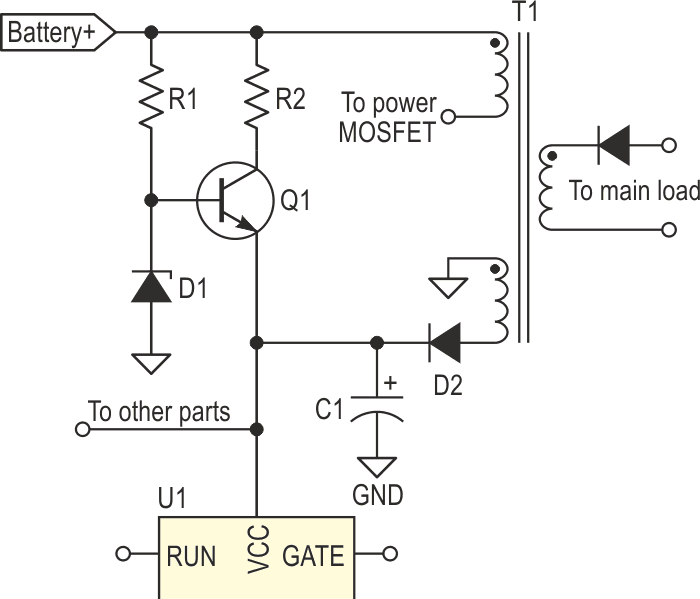
The light assembly contains both the LEDs and the electronic supply to power it. They show us the schematic, parts of it are in Figure 1.
 |
|
| Figure 1. | Part of the original schematic, drawn from memory. |
The input supply is 74 volts DC and comes from a battery. The unit is a non-isolated DC to DC step-down flyback converter that powers the built-in LEDs. It uses a controller IC, U1, with a separate power MOSFET, the MOSFET is not shown in my schematic. The MOSFET switches the primary of transformer-inductor, T1. There are two secondary windings on the transformer. The main winding goes to a rectifier and filter, not shown, and then to the LEDs, not shown. The auxiliary winding is rectified by D2 and filtered by C1. It then powers the controller IC. The main load is a series-parallel arrangement of red LEDs consuming 15 watts or so.
The controller cannot be powered directly from the battery supply because the voltage is above the IC maximum supply value. Also, since it sends gate signal to the MOSFET, it cannot be powered at more than 20 V or it will destroy the MOSFET.
The tail light designers figured that, if they connect U1’s VCC pin to the supply through a series resistor-shunt Zener circuit, the power lost to feed the IC will be more than 2 watts and it will lower the total efficiency by about 15%.
So they decided to use a start-up circuit that would power the IC momentarily and that once the converter is running, the IC will be powered from the converter’s output. They also need to shut-off that start-up circuit. They used a series resistor, R2, connected to the collector of a small signal high voltage BJT, Q1, with a sufficient voltage and current rating. Transistor Q1’s emitter is connected to the IC supply pin net, the same that the second secondary winding powers. The base of Q1 is connected to a Zener, D1, biased by a high value resistor, R1, from the input power. Once the converter has started and is running, the auxiliary winding voltage is rectified by D2 and filtered by C1. The VCC increases above D1 voltage and biases Q1’s base-emitter junction off. This cuts off the current and brings the start-up circuit losses to almost zero. Overall, half a dozen small signal parts cost much less than one or two high power parts, so the solution they chose for the start-up circuit makes sense.
The problem is that Q1 fails repeatedly. The converter starts up rapidly and the designer assures me that none of the parts overheat.
I immediately see the source of the problem, but I keep my mouth shut. If I tell them the solution now, they will pack up and not pay us for our expertise, arguing that the time we spent is not worth the paper work to pay us. My boss says we will work on it urgently.
They leave us a working unit and the schematics.
Once they have left the building, I talk to my boss. Designing the start-up circuit is a series of compromises: select a Zener value that is above minimum operating voltage for the IC, compute the number of turns on the transformer to produce a voltage above the Zener but not too high or it will damage the MOSFET. Adding to the problem is that the converter is regulating the main output current and not the auxiliary output voltage and has to operate over the whole range from the minimum to the maximum battery voltage.
If the running voltage from the auxiliary winding is much higher than the Zener voltage, Q1’s reverse-biased base-emitter junction can breakdown and destroy the transistor. Maximum VEBO is typically 6.0 V for the MPSA42, a transistor similar to Q1, and is typical of many BJTs. If the emitter-base junction reverse current level is low, the junction behaves as a Zener diode. With a higher current and a longer duration, the beta drops and the noise increases when normal operation is resumed. If the reverse current is excessive, then the transistor fails [1] [2], and that is why Q1 fails in this product.
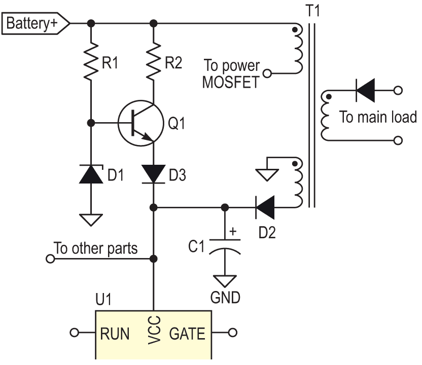
I tell my boss that the solution is simple, add a series diode, D3, between Q1’s emitter and the controller VCC pin, see the modified schematic in Figure 2.
 |
|
| Figure 2. | Part of the modified schematic, drawn from memory. |
He agrees with me. I modify the unit. I test it many times with on and off cycles, over the whole battery voltage range and the unit runs perfectly.
Late the next day my boss phones our client to say that we have identified the problem and have a simple and low cost solution for him. After a week our client informs us that the manufacturer has confirmed our solution to the problem and all they are both very satisfied with our work.
The lessons learned are:
- Beware of reverse biasing the base-emitter junction of a BJT.
- Do implement rigorous design reviews and use a list of items to check, the list here is a good start [3].
- Think before giving answers to customers, there is always money involved, your boss pays your salary with customer’s money, don’t give it away.
- And most importantly: never let the customer look like a fool.
References
- Pease, Robert A. Troubleshooting Analog Circuits. Butterworth-Heinemann, 1991. Page 77.
- Motchenbacher C. D. and J. A. Connelly. Low-Noise Electronic Systems Design. John Wiley & Sons, Inc. 1993. page 133.
- Wallace, Hank. Electronics Design Checklist, [Page retrieved 2022-06-19].