The circuit in this Design Idea was originally designed to detect damaged conveyor belts in the mining industry. Thin coils are embedded in the conveyor belt. If the belt suffers damage, it stretches at the affected location, causing one or more coils to break. The method for detecting the broken coil is to allow a “sensing” coil to magnetically couple with the passing coils in the belt, thus changing the total inductance of the magnetic pair. The sensing coil is part of an LC oscillator (Figure 1). When an intact coil passes the sensing coil, the frequency of the oscillator changes. If the conveyor belt moves at a fixed speed, the frequency of the oscillator modulates at a fixed rate. When a broken coil passes the sensing coil, there is more time between modulations (and this is what you want to detect).
 |
|
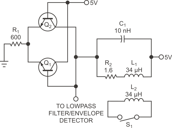
| Figure 1. | An oscillator generates a stable signal based on the values of L1, L2, and C1. |
The oscillator doesn’t generate a pure sine wave and is power-hungry but stable. It oscillates over a large range of LC pairs, even with a low quality factor and with almost any transistor. The amplitude is flat across a large bandwidth. The frequency is
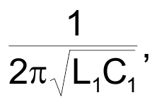
where L1 is the inductance of the sensing coil. R2 represents its resistance. L2 and switch S1 represent either undamaged or broken coils in the conveyer belt. When S1 is closed, the coils are undamaged, and when S1 is open, the coils are broken. When the coupling between the sensing coil and a conveyor coil is perfect, it is equivalent to having the two connected in parallel, which would reduce the total inductance and increase the frequency of oscillation.
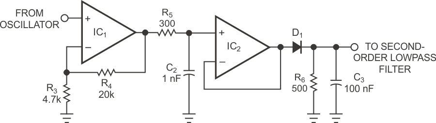
The problem now becomes how to detect different frequencies by implementing an FM demodulator or frequency-to-voltage converter. An easy way to accomplish this task is to pass the signal from the oscillator through an appropriately tuned lowpass filter. If the frequency range of the oscillator lies at the beginning of the roll-off, a higher frequency causes higher attenuation. At this point, an FM waveform has become an AM waveform, which you can easily demodulate using envelope detection.
 |
|
| Figure 2. | A lowpass filter changes the oscillator output into an envelope signal. |
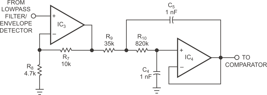
Figure 2 shows a trivial RC lowpass filter comprising R5 and C2 and driving the envelope detector comprising D1, R6, and C3. To find out whether the sensing coil couples to an external coil, you can check at the output of this circuit to see whether the voltage is above or below a certain threshold. You can experimentally determine the best value for the threshold. You can perform the comparison with an analog comparator or with a microcontroller after digitizing the signal. This last method would allow you to measure the time since the most recently detected undamaged coil passed. Figure 3 and Figure 4 show a simple and reliable analog method, using the envelope signal, to detect that a bad coil has passed. The output from the envelope detector contains ripple, so lowpass filtering allows a more precise discrimination in frequency. In this example, the filter in Figure 3 makes the ripple insignificant without deteriorating the frequency response of the system.
 |
|
| Figure 3. | A second-order lowpass filter removes ripple from the envelope detector’s output. |
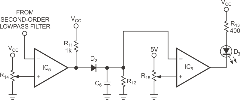
The output of the filter then feeds into the comparator (Figure 4). R14 sets the threshold, which should be at the midpoint between the generated voltages with and without an external coil coupled to L1. D2, C6, R12, and comparator IC6 behave as a countdown timer set to a time slightly longer than the period between passing coils. C6 quickly charges to a maximum voltage when a good coil passes and then slowly discharges. If the time between (sensed or detected) consecutive undamaged coils is below a certain maximum, the voltage across C6 should never go below the threshold that R15 sets, thus keeping the output of IC6 low and lighting LED D3. If a damaged coil passes, the oscillator’s frequency should remain the same, allowing the voltage across C6 to drop enough to trigger the comparator, turning off the “all-good” light.
 |
|
| Figure 4. | Comparator IC6 monitors the voltage across C6 and activates when the C6 voltage exceeds a preset value from R15. |
In a real-world application, you should latch the output to ensure that the operator notices the alarm condition. The circuit could simply shut down the power to the conveyor belt, allowing immediate repairs and indicating where the fault occurred. The circuit uses just a few common components with large tolerances on their values. Its use of transistors, op amps, discrete linear and nonlinear components, oscillators, filters, demodulators, converters, and magnetically coupled circuits make it an excellent teaching resource. It even gives some insight into how modern proximity-card technologies, such as RFID (radio-frequency identification) work.