Septimiu Pop and Ioan Ciascai, Romania
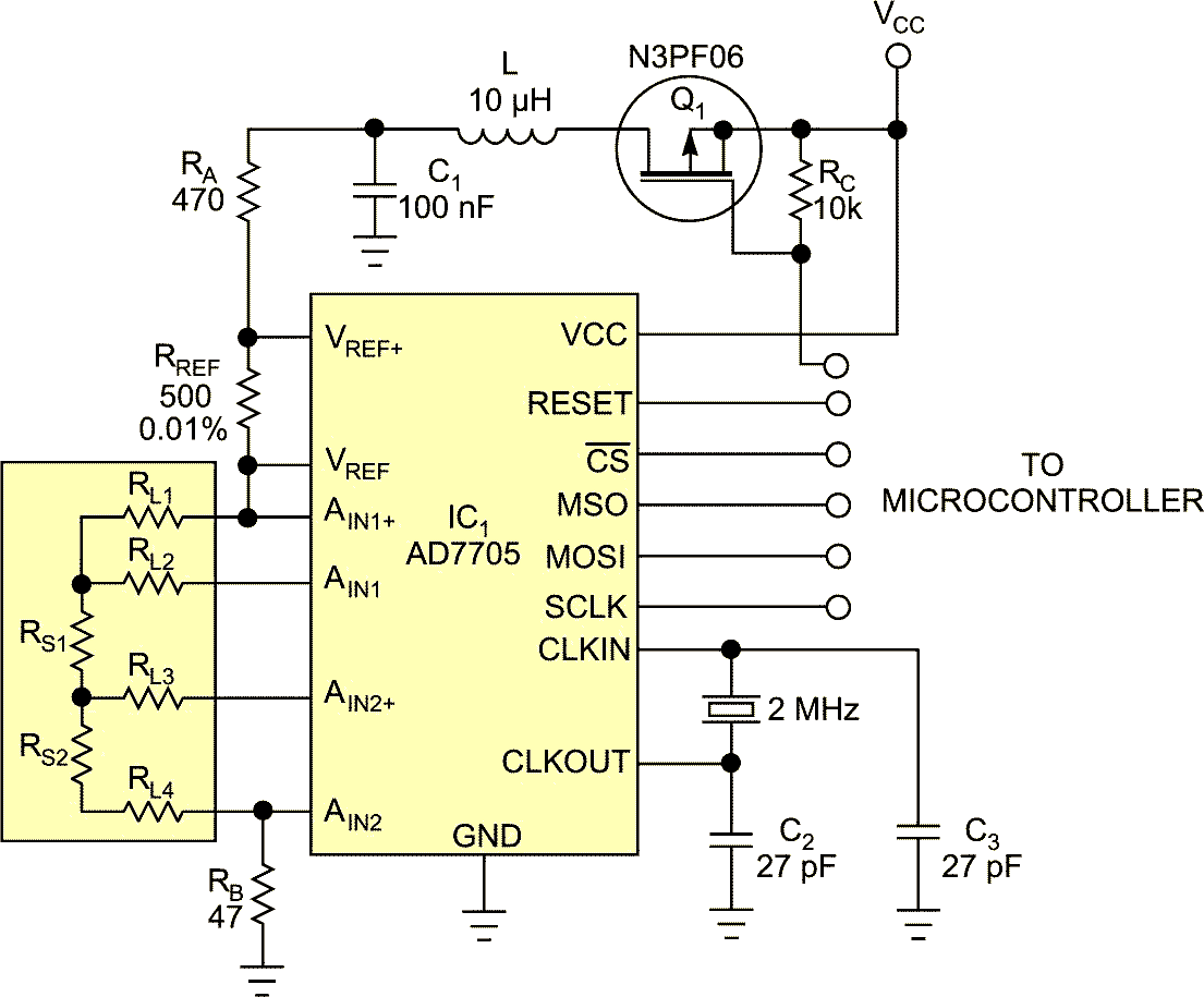
Resistive pressure sensors that use two resistive elements and four wires are useful in pressure-monitoring applications. When the pressure rises, one resistance rises and the other falls. Accurate measurements with resistive sensors require compensation for losses due to wire resistance, especially when wire lengths are tens of meters. The compensation method in this Design Idea relies on the equal resistance of wires: RL1 = RL2 = RL3 = RL4 = RL (Figure 1).
 |
|
| Figure 1. | A measurement circuit measures the values at three points, and a microcontroller can calculate the sensor values. |
A microcontroller or computer can calculate the resistance of the sensors using a differential voltage across sensor elements RS1 and RS2. Resistances RA, RREF, and RB and the sensor resistance limit the current through RS1 and RS2. To measure the sensor values, the circuit uses an Analog Devices AD7705 ADC, which has three pseudodifferential inputs that provide 16-bit resolution. In this application, the AD7705 operates in buffered mode—that is, the input bias current is less than 1 nA. In buffered mode, the analog inputs can handle large source impedances, but the absolute input voltage must be from ground plus 50 mV to the drain-to-drain voltage minus 1.5V. Resistance RB provides an input common voltage.
The measurements depend on the value of reference resistor RREF. For best accuracy, RREF must have a tolerance of 0.01% and must have a low temperature coefficient. To avoid sensor selfheating, you should pulse the excitation current; software through Q1 controls the pulse width.
The AD7705 performs the data acquisition through three channels. The sensors connect directly to the AD7705’s input channels, which make three successive acquisitions. Because the excitation current is the same in all sensor elements, the software computes each input voltage for the sensor elements in the following sequence:
- AIN1+, AIN1− compute RL;
- AIN2+, AIN2− compute RS2+RL;
- AIN1−, AIN2− compute RS1+RS2+RL.
You can compute the resistances RS1 and RS2 by subtraction. The AD7705 has a PGA (programmable-gain amplifier) that amplifies low input signals. The part contains self-calibration and system-calibration options that eliminate gain and offset errors in the part or in the system.
The pressure measurement also depends on both the resistance ratio and the temperature through the equation P=F(RS1/RS2,T). The parameter T is a compensation factor for the resistive sensors’ temperature dependence, T=F(RS1+RS2).