Temperature-indicator and temperature-based products have generated wide interest. There are numerous applications for such devices with many possible solutions, each with its own advantages and disadvantages.
This idea discusses a sensor interface that offers high accuracy while using less board real estate. The article also discusses some software issues and provides code samples that users can integrate into their system and adapt to their environments. Designers can add to the features offered by the circuit as well.
The simple circuit interfaces a 1-Wire temperature sensor (DS18S20) to a Cypress microcontroller (CY8C26443). But the technique can be extended to any other 1-Wire device with little modification of the hardware and code. The MCU can be any processor, but I chose a programmable system-on-a-chip (PSoC) because it offers flexibility in terms of choosing and implementing hardware blocks on the silicon. The PSoC also provide an application program interface (API) so novices can easily work on and troubleshoot their ideas.
The 1-Wire products provide functions such as memory and mixed-signal capabilities via a single wire over a serial interface, with both power and communication delivered using the serial protocol. These devices are easy to interface and use where minimum interconnect complexity is required.
I chose the DS18S20 digital thermometer because it is a very cost-effective 1-Wire device and has an accuracy of 0.5°C, although the overall design achieves 1°C of accuracy including measurement error due to hardware limitations and test tools, etc. The DS18S20 also supports parasitic power mode, has a programmable temperature threshold, and operates from –55°C to 125°C. With additional hardware and software, it can operate over a distance of a few feet.
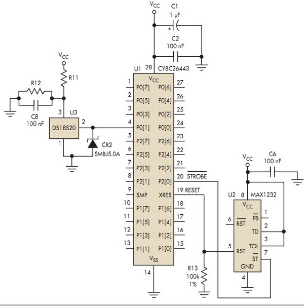
Using the DS18S20 in the TO-92 package, pin 1 is connected to ground, pin 2 is the open-drain 1-Wire interface pin used for data input/output and power, and pin 3 is connected to VCC or, if the parasitic power mode is used, to ground. For the device in an SO-8 package, the corresponding pins are 5, 4, and 3, with the remaining pins not connected. Figure 1 shows the circuit schematic. Since the circuit uses power from the board, the device is connected to VCC.
 |
|
| Figure 1. | Although this circuit connects the DS18S20 1-Wire temperature sensor to a Cypress CY8C26443 PSoC microcontroller, designers can easily adapt it to connect other 1-Wire devices to any microprocessor. |
This version of the interface connects the DS18S20 directly to the MCU, essentially on the printed-circuit board (PCB) as if the sensor was part of the microcontroller. The board size assumes that parasitic components are negligible and have no effect on the signal.
Using the PSoC, you can either instantiate the 1-Wire module for the interface or write your own protocol. Instantiating the module reduces the software overhead, but I chose to write my own protocol. Although this added firmware overhead, I avoided using a two-port pin, which the PSoC module requires for data exchange between the MCU and the sensor.
The circuit is very simple. CR2 protects the sensor from surges. R12 is not used in the normal mode. In the parasitic mode, R12 is inserted and R11 and C8 are out. U2, a MAX1232 microprocessor supervisory circuit, is a reset controller and the MCU will strobe it at regular intervals.
This code blocks for this interface circuit, along with comments. The PSoC integrated development environment is available without charge from www.cypress.com.
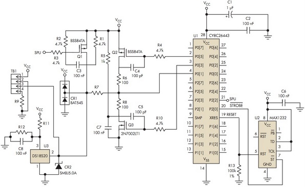
For use at longer distances, the circuit can be extended over several feet with the modifications shown in Figure 2. The additional components ensure that enough source and sink currents are passed through so the timing parameters can be maintained.
 |
|
| Figure 2. | With some added components that ensure enough source and sink currents to maintain timing parameters, the sensor can operate up to several feet away from the MCU circuitry. |
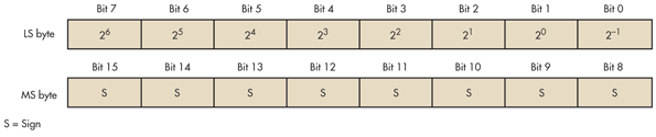
The temperature sensor converts and stores the digital data in two registers (Fig. 3). Essentially the resolution of the readout is 9 bits. The least significant byte stores the temperature readout. The most significant byte provides the sign for the readout. In the case where the sign bit is negative (0xFF), the LSB data is two’s complemented. Bit 0 in LSB provides the decimal value for temperature: 0.5°C for a logic 1 and 0 for a logic 0. Software is needed to take steps to avoid erroneous readings.
 |
|
| Figure 3. | The sensor stores digital data in two registers. The least significant byte holds the temperature readout. The most significant byte provides the sign for the readout. |
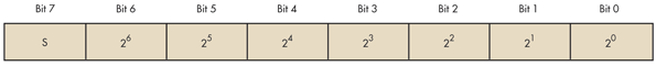
The circuit also includes nonvolatile (EEPROM) memory locations, a TH and TL register, to store high and low threshold levels. After the DS18S20 performs a temperature conversion, the temperature value is compared to the user-defined two’s complement alarm trigger values stored in the 1-byte TH and TL register (Fig. 4). The TH and TL register resolution is 8 bits, as opposed to 9 bits for the temperature conversion register.
 |
|
| Figure 4. | If required by the application, the sensor interface can include a nonvolatile memory (EEPROM) register to hold high and low threshold two’s complement alarm trigger temperatures. |
The circuit’s memory map includes a SRAM scratchpad with nonvolatile EEPROM for the TH and TL register (Fig. 5). If the alarm trigger function is not required, the TH and TL register can serve as general-purpose memory.
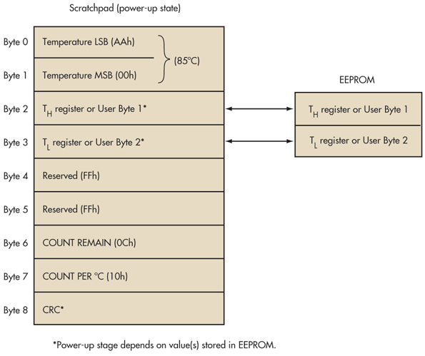 |
|
| Figure 5. | Besides the EEPROM register for the high and low alarm triggers (TH and TL), the DS18S20’s memory includes a SRAM scratchpad. |
Resolution greater than 9 bits can be calculated using the data from the registers in the scratchpad - temperature, COUNT REMAIN, and COUNT PER °C:
![]()
where:
Temperature = resolution higher than 9 bits
TempRead = temperature obtained by truncating the 0.5°C bit (bit 0) from the temperature data
Count Per °C = COUNT PER °C (byte 7 from scratchpad) = 16 (0x10)
Count Remain = COUNT REMAIN (byte 6 from scratchpad).
Downloads
Schematic Diagram on Figure 1 (PDF) - download
Schematic Diagram on Figure 2 (PDF) - download
Source Code for PSoC (PDF) - download