Gunther Kraut
Logic 1, logic 0, and high-Z make for three possible states: forward, reverse, and off
Independently switching two loads, such as relays, usually requires two microcontroller-I/O ports. Two ports let you control the loads so that you can switch them both off, switch them both on, or switch one on and the other off. If you don’t need both relays on at once, you can control the remaining three states using only one port. You can also use a port’s high-impedance state to control the relays.
You can, for example, use this application to control a motor. The motor’s rotational direction depends on which of its two phase lines you select. This approach works with either classic electromechanical relays or SSRs (solid-state relays). If both relays are open, the motor is off.
 |
|
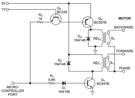
| Figure 1. | Relays respond to logic one, logic zero, and the high-impedance states of the microcontroller port. |
For electromechanical relays, you can use the driver circuit in Figure 1. Setting the microcontroller pin to logic one causes Q1 to turn on relay REL1, and the motor runs forward. Setting the pin to a logic zero turns on Q2, which turns on Q3. This action closes the switch of REL2 and causes the motor to run in the opposite direction. If the microcontroller port is in a high-impedance state, Q1, Q2, and Q3 cannot deliver current because the constant voltage of 1V at the base of Q2 is too low to reach the threshold of the base-emitter junctions of Q1 and Q2 plus the diode drop of D1. Both relays are off, and the motor is off. The supply voltage through a voltage divider or an emitter-follower circuit can provide the constant voltage of 1V. Free-wheeling diodes D2 and D3 prevent the collectors of Q1 and Q2 from overvoltage when the relay’s coils are off. You can use almost any small-signal NPN and PNP transistors in this circuit. The selection of diode D1 is also not critical.
 |
|
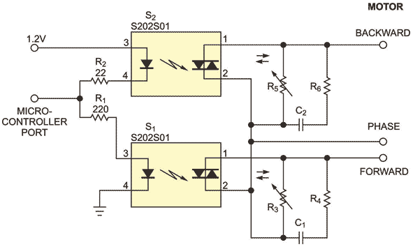
| Figure 2. | The circuit is simpler for SSRs because virtually all microcontroller ports directly drive the LEDs. |
The circuit is simpler for SSRs because virtually all microcontroller ports directly drive the LEDs (Figure 2). A logic one supplies the LED in S1, whereas a logic zero supplies the LED in S2, making the corresponding TRIAC (triode-alternating-current) switches conductive. If the port is in the high-impedance state, no current can flow through the LEDs because the constant dc voltage of 1.2V is below the sum of the threshold voltages of the LEDs. Voltage-dependent resistors R3 and R5 and snubber circuits C1, R4, C2, and R6 protect the SSRs. These protection circuits’ values depend on the respective load.