Dušan Ponikvar, University of Ljubljana, Ljubljana, Slovenia
EDN
Often a measurement of weak signals has to be performed in the presence of strong interference from the ac power mains. If the interfering signal cannot be filtered out, then you can still obtain a clean result by making two consecutive measurements separated in time by an odd number of half-periods of the mains and calculating the average of the two measurements. The interfering signals have opposite polarities in consecutive measurements, and averaging cancels them out. If you average several consecutive pairs of measurements, the results will improve still further. Instead of counting the half-periods of the mains, you may find that a circuit having two outputs for synchronization with odd or even half-periods of the mains can come in handy.
 |
|
| Figure 1. | Mains zero crossings are marked by the optically isolated outputs. |
The circuit shown in Figure 1 provides two separate and optically isolated outputs, ISO1 and ISO2, for synchronization with the desired half-period of the mains. Figure 2 shows the results of simulation (using the free version of TINA-TI). The circuit accepts mains input from 80V ac to 240V ac, and consumes less than a milliamp of current.
 |
|
| Figure 2. | Simulation results demonstrate the circuit action. |
The duration of the pulses at outputs ISO1 and ISO2 is less than a millisecond, and capacitor C1 can be adjusted to achieve the exact alignment of the falling edges of outputs ISO1 and ISO2 with the zero crossing of the mains. All diodes, D1 to D5, are small-signal type 1N4148 or similar.
The circuit works as follows: During the positive half- period of the mains, C3 is charged through R1A, R1B, D1 and D5, D3, R2B, and R2A. The effective time constant, t, for charging is about 43 msec, and C3 barely picks up some charge in the half-period. Once the mains drops below the voltage stored on C3 (this happens just before the end of the half-period), the charging stops and current begins to flow from C3 through R3 into the base of Q5, turning it on. This discharges C3 through the LED in optocoupler OC1, and produces a pulse at the output ISO1 of the circuit. During the negative half- period, the action repeats, only this time D4 and D2 are used to charge C2, and R4 is used to activate Q5 when the negative half-period is nearly finished.
The duration of the output pulse can be shortened to about 600 µsec by increasing the time constant – therefore by increasing the value of resistors R1 and R2 or capacitors C2 and C3 – but this also reduces the range of acceptable input voltages.
The detailed simulation reveals that the maximum voltage on C2 and C3 is less than 5V, with 250V ac connected to the input; a voltage rating of 10V for the capacitors is sufficient. Additionally, the maximum voltage on C1 is less than 10V ac, and the reverse voltage on the diodes is less than 6V. The peak current through the optocoupler LEDs is below 8 mA. The only components that are exposed to the mains are input resistors R1A, R1B, R2A, and R2B. They have equal values, so each one needs to withstand 25% of the mains voltage.
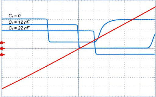
The measurements obtained from the constructed circuit show good correlation with the simulation results. Figure 3 shows output signals; Figure 4 shows the timing detail of the zero crossing and corresponding output pulse for three different values of C1.
 |
|
| Figure 3. | Measured output signals ISO1 and ISO2 and the mains voltage verify the circuit operation. |
 |
|
| Figure 4. | C determines the position of the pulse leading edge in this detail from the center portion of Figure 3. The horizon- tal scale is 200 µsec/div. Pulses are vertically shifted for bet- ter visibility. |
REFERENCES
- “DIY: Isolated high-quality mains voltage zero-crossing detector,” www.dextrel.net/ diyzerocrosser.htm.
- Matteini, Luca, “Mains-driven zero-crossing detector uses only a few high-voltage parts”, EDN, Dec 1, 2011, www.edn.com/4368740.