This all-analog circuit provides three key waveforms simultaneously and at the same frequency within the audio band. It is useful for evaluating audio systems, transformers, cables, and other electrical installations.
This simple, robust, and low-cost signal generator, based on the LM386 power amplifier IC, provides a trio of audio-band signals with three different simultaneous outputs at the same frequency: square/rectangle (SQW), triangle (TRG), and sine (SS).
Each output can drive loads such as long cables, transformers, auto-transformers, audio couplers, or active loudspeakers. The amplitude of each output can be adjusted independently. The outputs can be connected to ground, the power supply, or between them for short time without damage.
The generator is useful for checking electrical or audio installations, audio or mains transformers, and similar components. The suggested maximum load for each output is 8 Ω, but lower-impedance loads also can be handled with some reduction in output. As a further convenience, the user can switch the output triplet between two frequencies.
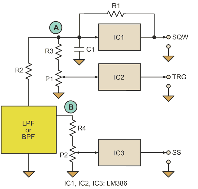
The simplified block circuit shows IC1 operating as a square-wave generator with frequency determined mainly by R1 and C1 (Fig. 1). The signal in point A is approximately triangular with amplitude of about 0.35 V p-p and a supply rail of +9 V.
 |
|
| Figure 1. | The block diagram shows how three low-power audio amplifiers (LM386) are configured to implement a triple-waveform generator at one of two selectable frequencies. |
The triangular signal goes to amplifier IC2 via potentiometer P1. It is also routed to the low-pass filter (LPF) or a band-pass filter (BPF). The quality of that filter determines the quality of the sinusoidal signal, which IC3 amplifies.
The 3-dB frequency of the LPF should be equal to or lower than the frequency of the triangular signal at point A. With a BPF, the central frequency or the resonant frequency should be approximately equal to that of the signal at the same point. In the simplest case, these can be second-order low-pass RC, RC band-pass, LC band-pass, or LC low-pass filters. IC3 amplifies the sinusoidal signal at point B, after potentiometer P2.
IC2 and IC3 are used with a gain of 200. This may result in trapezoidal-like signals at outputs TRG and SS when the input signals are too large and the amplifiers are saturated. If this is a problem, then the gains of IC2 and IC3 can be set to approximately 50 as described in the IC data sheet.
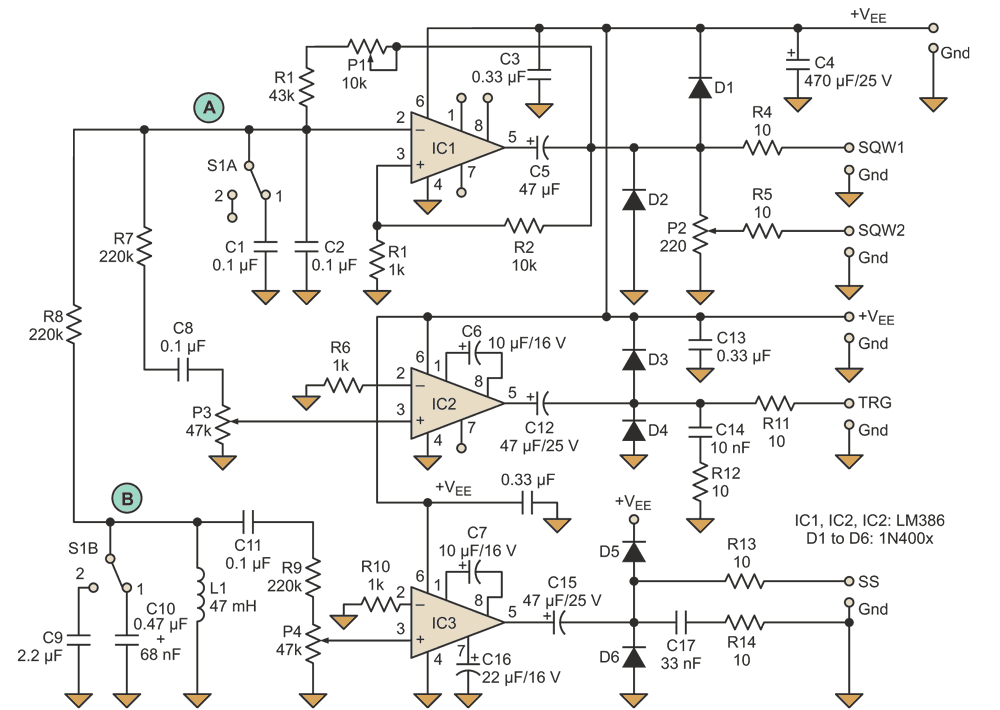
The actual circuit of the generator is built with three LM386 ICs. It produces two frequencies, selectable via double-pole double-throw (DPDT) switch S1 (Fig. 2). When the switch is in position 1, the frequency is 1 kHz. In position 2, it is 500 Hz. Trimmer potentiometer P1 is used to fine-adjust the nominal 1-kHz frequency, while the 500-Hz output is not adjustable, for simplicity.
 |
|
| Figure 2. | The frequency of the simultaneous square, triangle, and sine waveforms can be switched between two values (here, 500 Hz and 1 kHz) via DPDT switch S1, which selects the capacitor for the resonant LC tank. |
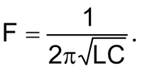
IC2 amplifies the triangular signal from point A via potentiometer P3. It also goes to the band-pass LC filter built with C9 (or C10) and L1. The resonant frequency of L1/C9 is around 500 Hz, while the resonant frequency of L1/C10 is 1 kHz, with C10 implemented as two capacitors in parallel (0.47 µF + 68 nF). The resonant frequency F of the LC tank can be approximated using the standard formula
Depending on the position of the wiper of the P3, output TRG will be triangular or trapezoidal, with the maximum amplitude limited by the power supply. The square-wave signal is available at the outputs SQW1 (non-adjustable amplitude) and SQW2 (adjustable amplitude with the potentiometer P2). The sinusoidal signal at point B is connected via potentiometer P4 to be amplified by IC3. The amplified signal is available as output SS.
The internal noise of the chosen LM386 may not specified, so its gain should be minimized. The values of R1, R7, R8, R9, P3, and P4 also should be minimized to minimize noise. The LM386 amplifier is available from different sources with some variations in specifications, such as an operating supply range from 4 to 12 V or 5 to 18 V. Typical and maximum output power is a function of the LM386 chosen, as well as operating voltage and load impedance.