While creating an infrared beam intrusion detector system, the need for a beam-focusing method became evident. Parts from a modified Genie garage door Safe-T-Beam system, purchased at the local home improvement store, proved to be perfectly suited to the application. The main reason for choosing the Genie unit is that the IR transmitter and receiver housings each contain a plastic lens inside a short plastic tube molded into the housing. The tube and lens help to shield and focus the beam, simplifying installation of the intrusion detector.
The circuit for the IR transmitter, integrated into the Genie’s motor mechanism, uses a pulsing signal to facilitate beam focusing. The design for the intrusion detector called for a modulated CW signal. However, modulating the IR beam makes the system impervious to sunlight interference.
As a result, the pulse circuitry inside the motor mechanism was not used and the transmitter components could be replaced. Installing the new IR transmitter circuit board in a piggyback fashion inside the transmitter housing allowed reuse of the IR diode’s original mounting.
The IR transmitter circuit utilizes two LM555C timer ICs, U1 and U2 (Fig. 1). Timer U1 produces a 40-kHz signal, and U2 modulates that signal at about 1600 Hz. There’s nothing critical about these choices. Other frequencies could serve as well.
 |
|
| Figure 1. | Replacing the original pulsed signal transmitter circuit in the garage door IR safety system with a modulated carrier signal, and using the receiver circuit virtually intact, provides this intrusion detector with daylight noise immunity. |
Even though the transmitter circuit needed replacing, the receiver circuit could be used virtually intact. The IR receiver module captures the modulated IR beam and presents the detected 1600-Hz modulation signal at the DATA pin. From there, the signal goes to Q102, which amplifies and squares up the pulses.
Resistors R102 and R108 and capacitor C105 filter the pulses to provide a smooth signal to the base of Q101. Because a 1600-Hz modulation replaced the original pulsed signal, the filter capacitor C105 had to be changed to 0.0047 F. The other change was to replace the original Q101 and Q102 with known devices to facilitate debugging. However, the original p-n-p and n-p-n transistors should work just fine.
When the intrusion detector is operating normally, the received signal holds the collector low on output transistor Q101. When the beam is broken, the loss of signal causes Q101’s collector to go high. Thus, intrusion detection is active-high. A simple modification of this circuit would allow for an active-low output.
 |
|
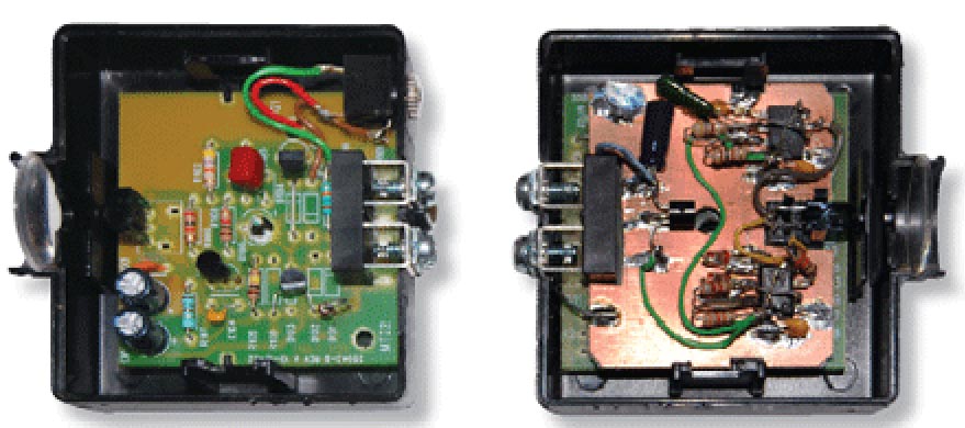
| Figure 2. | Shown is the completed IR detector setup. Alignment of the transmitter and receiver is crucial to achieve the proper output. |
Aligning the transmitter and receiver is not a difficult task, although it can take a little adjusting to get the beam centered on the receiver (Fig. 2). Over reasonable distances, a measuring tape stretched between the two will help get the alignment close. The rest is a matter of trial and error. The detector’s output will be high when misadjusted and will go low when proper alignment is achieved.