Ricardo Jiménez and Juan C. Ángeles
Electronic Design
A basic microcontroller can be used to convert a sensor's analog output into a pulse train, thereby making the output compatible with standard digital I/O ports.
When the need arises to convert voltage readings from an analog sensor into a pulse train, a low-end microcontroller offers a versatile solution. The design in Figure 1 uses an 8-pin PIC12F683 to provide a pulse train that’s proportional to the sensed input voltage. This is useful, for example, when transforming a sensor signal into a format that’s compatible with a basic digital or GPIO input. The output operating range ranges between 0 to 500 pulses for an input voltage of 0 to 5.00 V dc.
 |
|
| Figure 1. | In the voltage-to-pulse train converter design, the train on GP2 is proportional to the sensed voltage on AN3; a counter detects the pulse train, which is then decoded and multiplexed to a common-cathode LED display. |
An input voltage (VIN) of 1.25 V dc, for example, will generate a pulse train (Pt) of 125, which is defined by the equation:
Pt = VIN × 100,
where VIN is in volts, decimals, and hundredths. In this design, each pulse has a period of 1 ms with a 50% duty cycle. The refresh time (Rt) is given by:
Rt = VIN × 1 ms + 50 ms delay.
The longest refresh time of 0.499 seconds (plus 50-ms delay) occurs for a 4.99-V reading, while the shortest one of 51 ms corresponds to an input voltage of 0.01 V. The 50-ms delay added to all readings is needed to avoid a flickering display.
In the circuit, an analog input voltage delivered by a 47-kΩ trimming potentiometer is applied to the microcontroller’s analog Input (AN3). The internal analog-to-digital converter (ADC) is configured to 8 bits, providing a precision of ±19.60 mV, with a resolution of 100 mV.
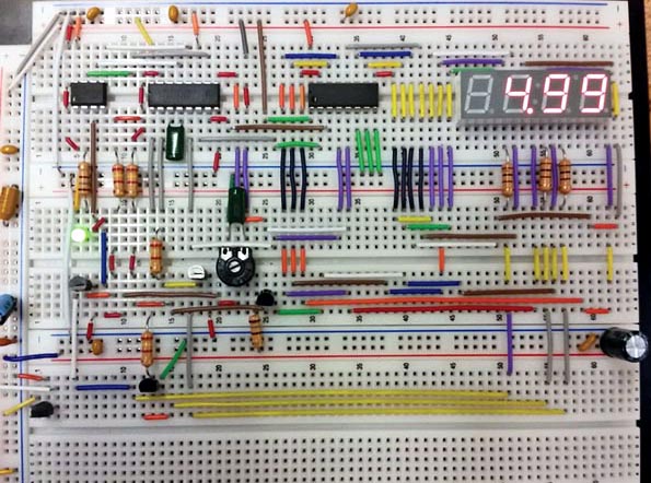
To test the MCU program, the circuit includes a 3-digit BCD counter using an MC14553 to count the pulse train. The train is latched in the counter and decoded with a MC14543 (CD4543) to drive a four-digit multiplexed LED Display (Lite-On Inc. LTC-4727JR) via three switching transistors. Figure 2 shows the actual circuit assembled in a prototyping board.
 |
|
| Figure 2. | Due to absence of layout-critical wiring or RF issues, the circuit was assembled and tested on a standard prototyping board. |
To generate a pulse train on GP2 proportional to the input voltage, the algorithm (see the listing below) takes a voltage reading and makes a conversion to decimal with the LSB constant equal to 19.60. It then gets its equivalent in digital format for the units, decimals, and hundredths, using the instructions DIG3, DIG2, and DIG1, respectively. The DIG1 value is stored in variable “units” to create a loop that generates that number of pulses. Similarly, the DIG2 value is multiplied by 10 and stored in a variable called “decimals” to generate the tens of pulses. Finally, the DIG3 value is stored in the variable called “units,” which is multiplied by 100 to generate the hundreds of pulses required for the reading.
 |
|
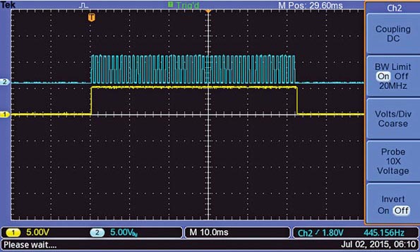
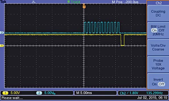
| Figure 3. | The timing diagram shows a pulse train being generated; the yellow pulse stays high during the pulse train transmission. |
In this way, for example, a voltage reading of 2.54 V will be composed of 4, then 50, and then 200 pulses, to get a total of 254 pulses with a period of 1 ms. Therefore, it takes approximately 254 ms to transmit this pulse train. If one of the digits is equal to zero, the program skips that loop. Figure 3 shows a pulse train with its corresponding output generated by GP5.
 |
|
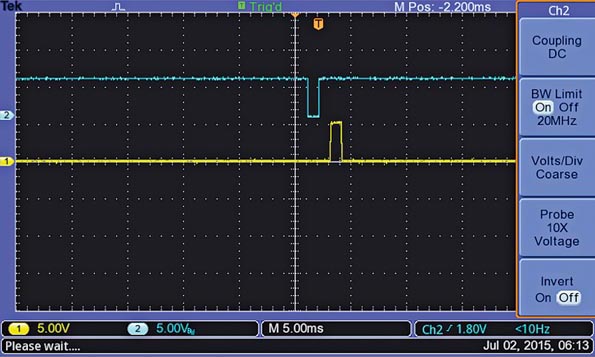
| Figure 4. | The Latch and Reset pulses generated by the microcontroller at the end of a pulse train are used to store a reading and clear the counter, respectively. |
Once the pulse train is finished, a 1-ms latch (active low) pulse on GP0 is transmitted to store that reading in the MC14553’s internal latches. Then a second (active high) 1-ms pulse on GP1 is generated to clear the counter to all zeroes (Figure 4). The latch in the MC14543 decoder is set to transparent mode. Output GP5 is used to indicate when the MCU is transmitting the pulse train.
 |
|
| Figure 5. | For a reading of 0.11 V dc, the MCU generates 11 pulses, which are then followed by a Latch pulse to store the reading. |
Three PNP transistors 2N2907 (Q1 to Q3), which continuously scan the data to the LED display, are controlled by the MC14553 counter. Transistor Q4 activates the decimal point, providing a 5-V pulse only when /DS1 is pulsed low. Figure 5 shows the 11 pulses generated for a voltage reading of 0.11 V dc, and the latch pulse generated at the end of the pulse train.
For higher-precision applications (such as 4.88 mV per LSB), you can configure the ADC to 10 bits. In this case, the output-signal period might be reduced to 0.5 ms to avoid having longer delays when the input voltage is at maximum. In such a case, a 1.000-V dc reading would generate 1000 pulses. For battery-operated applications, a numerical liquid-crystal display is recommended, which requires using three MC14543 decoders.