Jim Brannan
EDN
Combining PWM with a small R-2R ladder improves both. It reduces PWM ripple significantly and increases the DAC’s resolution.
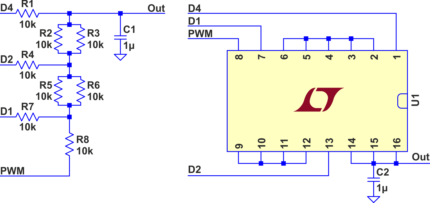
In this Design Idea, an eight-resistor array and three output pins construct a modified R-2R ladder (Figure 1). The modification is to connect the bottom 2R to a PWM output rather than to ground.
 |
||
| Figure 1. | Hybrid PWM/R-2R DAC. | |
The ladder divides VCC into eight slices, with the PWM filling the space from each level (0% PWM) to the next higher one (100% PWM). This reduces ripple to one eighth, while adding three extra high-order bits of resolution. Alternatively, you can take those three bits from the top of the original PWM duty-cycle value, multiplying its clock rate by eight. You still get the 8:1 ripple reduction, but the increased clock rate pushes PWM noise further out into the lowlands of the filter for greater attenuation.
Simulation
I have simulated this hybrid approach.
 |
||
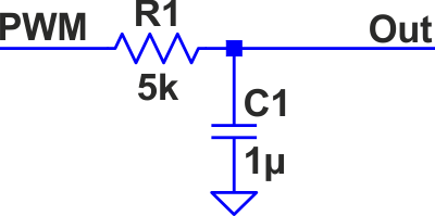
| Figure 2. | Comparison/simulation circuit. | |
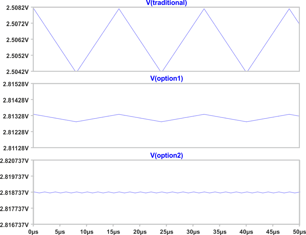
To compare with the traditional simple low-pass filter (Figure 2) you should remember that the output resistance of an R-2R ladder is R, and since I propose paralleling two resistors from the array to form R (with individual resistors for 2R), a 10 kΩ array yields 5 kΩ output resistance. That is what I used for the traditional approach along with the same 1 µF capacitor. I set the PWM to 50% duty cycle as that is where the worst ripple occurs. The results of the simulation (Figure 3) show the traditional approach with about 4 mV of ripple, while the first option (adding the three new bits to the original eight) resulted in 493 µV of ripple, just about one eighth. The second option (increasing the PWM clock by eight, leaving eight bits total) generated only 61 µV, around one sixty-fifth of the original.
 |
||
| Figure 3. | Simulation results. | |
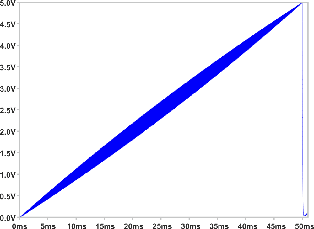
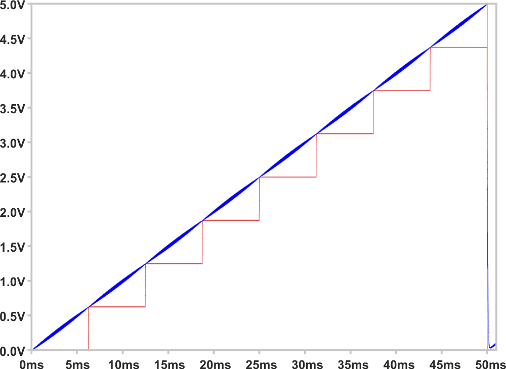
Figures 4a (PWM + low-pass) and 4b (11-bit hybrid) are the results of a complex simulation which slowly steps the voltage from 0 V to 5 V. The capacitors in the filters are deliberately too small so we can see the ripple at this scale. A normal R-2R ladder adds a stair-step graph (Red in 4b) to show how the PWM moves from one level to the next, and even beyond the top of the R-2R ladder up to 5 V.
|
||||||
| Figure 4. | Simulated ripple of basic PWM DAC (fig4a, top), and hybrid DAC (fig4b, bottom). |
|||||
This would also work with the NCO (numerically-controlled oscillator) technique in place of PWM. NCO (add a value to an accumulator and output the carry) has the advantage over PWM because it reduces ripple around the 50% setting (by increasing the frequency of transitions), which is where simple PWM is the worst.
And this can also work with any other DAC: just connect the PWM/NCO/whatever signal to the least significant bit position.
Testing
Now for some test results: The resistor array that I was considering has a tolerance of ±2%, but can also be obtained in ±1% and even ±½%, but since I didn't have any of those, I just used individual 1% resistors. I set up timer1 of an ATmega328 running at 16 MHz for 8-bit PWM, and used the 10-bit ADC to take some measurements. Since PWM, R-2R, and ADC are all referenced to VCC, we can factor it out and just examine the values read from the ADC for each of the eight levels, with PWM set at 0% and 100%. Ideally, the 100% entry of one step should equal the 0% entry of the next (with the caveat of any ADC reading being off by up to two, as described in the “ADC characteristics” section of the ATmega328 data sheet).
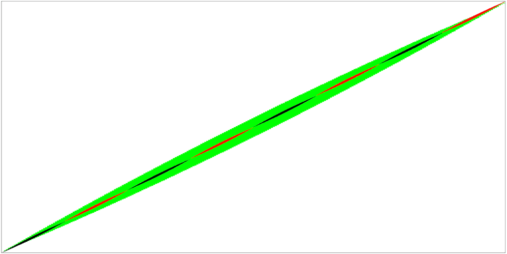
These seem to be quite reasonable. I then used a technique I've nicknamed “Slow-scilloscope™”, which uses the ability of the ATmega328 to schedule an A-D conversion with a timer – the same timer that is producing the PWM. Thus we can measure ripple across a given PWM cycle. Figure 5 is a composite graph of both the traditional PWM with low-pass filter (Green) and the hybrid (Black+Red). Both use capacitors that are way too small so we can see the ripple.
 |
||
| Figure 5. | Measured ripple of PWM & hybrid DACs. | |
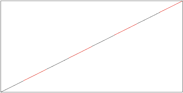
Finally, Figure 6 is a (boring) trace of non-synchronized A-D conversions at each hybrid setting, allowing the ripple to make (more or less) random variations in the result. This one uses a larger capacitor for more realistic results.
 |
||
| Figure 6. | Measured ripple, hybrid DAC, final capacitor value. | |
In the end, we have seen that, depending on your point of view, PWM can fill in the spaces between an R-2R DAC’s steps, or an R-2R ladder can drastically cut the ripple of the usual PWM plus low-pass filter. Or both.