Mikhail Shustov, Tomsk
Theoretical bases and practical diagrams of stable current generators with a variable or step action of terminal current from 1 µA to 10 nA are given.
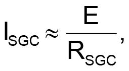
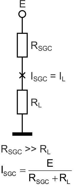
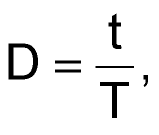
A stable current generator (SCG) is an electronic circuit designed to provide a constant current through a load regardless of its resistance. To fulfill this condition in series with the load resistance RL include resistance RSCG, Figure 1, where RSCG >> RL. Under this condition the current through the load can be determined from the expression:
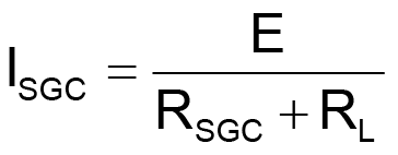
or
Where, E is the power supply (the source resistance is neglected).
 |
||
| Figure 1. | A classical diagram of the simplest stable current generator. |
|
Both the high-resistance resistors and the more complex circuits with semiconductors (transistors, chips) and the other elements are used as SCG [1, 2].
A common disadvantage of the previously known SCG is the difficulty of adjusting the stabilized current through the load, as well as providing ultra-low currents through it.
The SCG presented below contain two new technical solutions capable of solving this problem. The first is the use of a "drip" mechanism of SCG current formation; the second is the possibility of the Vernier expansion of the current control range by 1-2 orders of magnitude.
 |
||
| Figure 2. | The operation principle of the drip type SCG. | |
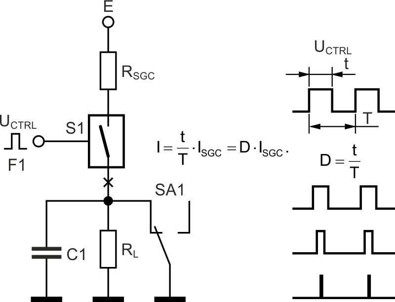
Figure 2 shows the operation principle of the drip type SCG. Key element S1 controlled from a square-pulse generator with a variably or discretely adjustable duty factor D (Duty cycle) is included in the break of the circuit RSCG, RH):
where
t – time; T – the pulse period.
As a result, the current through the load resistance is equal to
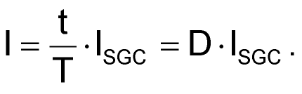
If the duty factor is adjusted discretely at a pitch of 1%, the load current can be changed steppably within two orders from 0.01 to 1.00 of ISCG.
Capacitor C1 is designed to smooth current ripples in the load, where the load itself to avoid the current discharge surge through it is preferable to switch on with (switch) SA1.
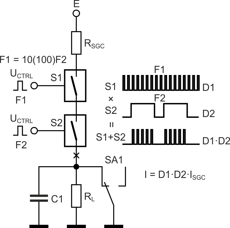
Figure 3 shows the possibility of more subtle current adjustment of the drip type SCG due to the Vernier electronic analogue. Vernier is a mechanical or electronic device designed for smooth or steppable expansion of the adjustment range or measurement of precision instrumentation and other devices.
 |
||
| Figure 3. | The operation principle of the Vernier two-stage drip type SCG. | |
To implement the Vernier stretch range of the SCG current control, the second switch S2, connected in series with the first one S1, is introduced into the circuit, figure 3.
The control signal frequencies of the switches should differ in 10 (100) times that will provide an adjustment range stretching by1 (2) orders of magnitude. At the switches outputs without bulk capacitor C1, the pulse packets adjustable in width both of the packets themselves and of the high-frequency pulses inside the packets will be observed.
Provided that control pulse modulation coefficients D1 and D2 of switches S1and S2 are adjusted, respectively, in equal ranges from 0.01 to 1.00, the current through the load resistance can be defined as
I = D1∙D2∙ISGC = 0.0001…1.00∙ISGC.
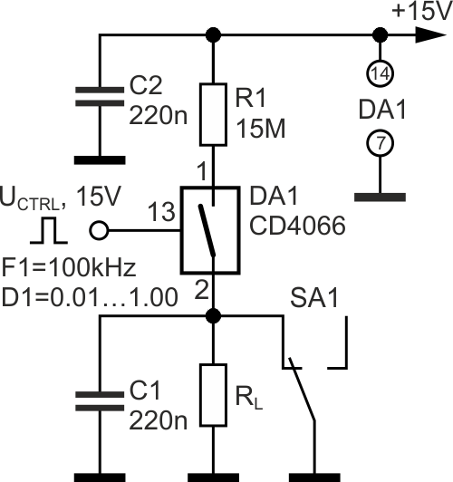
The practical scheme of the simplest variant of drip type SCG is shown in Figure 4.
For example, a generator [3], powered by a voltage of 15 V can be used as the control signal generator with a smoothly variable modulation coefficient from 0 to 100%.
 |
||
| Figure 4. | The drip type SCG providing the adjustable current in the load circuit from 1 µA to 10 nA |
|
Figure 5 shows the practical scheme of the Vernier drip type SCG for the range of the load currents 10–6...10–11 A. Another innovation is used in this SCG: a current splitter in which 90% of the current flows through one of the splitter blocks, and 10% through the load circuit. In this case the load resistance should not exceed 0.01(R2+R3) or 6...7 kOhm. For SCG (figure 4 and figure 5, SA1 in position ×1.0) the load resistance should not exceed 150 kOhm, or not more than 1% of nominal resistance R1.
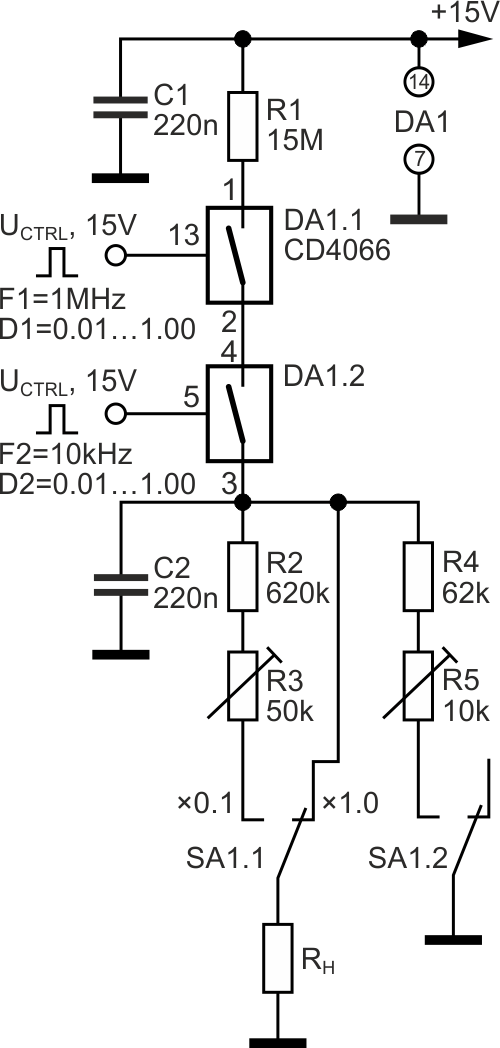 |
||
| Figure 5. | The Vernier drip type SCG, providing adjustable current in the load circuit from 1 µA to 100 pA with the possibility of step-down current in the load by an order of magnitude. |
|
Since the switching transients and switching persistence of the switch keys can make distortions in the SCG operation, too high frequencies should not be selected at designing a SCG.
Let us note that in the Vernier drip type SCG the additional current staging into "drops" and their series can be used, as well as multiple current splitters. Not only high resistance resistors, including higher ratings, but also the other bipolar current generators can be used as RSCG.