Noel McNamara
EDN
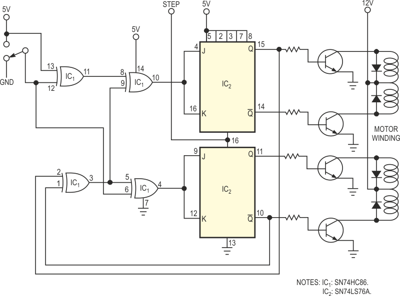
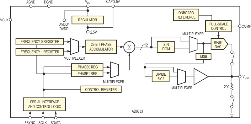
Stepper motors are useful in many consumer, industrial, and military applications. Some, such as personal-transportation systems, require precise speed control. Stepper-motor controllers can be simple (Figure 1), but they require a variable-frequency square wave for the clock input. The AD9833 low-power DDS (direct-digital-synthesis) IC with an on-chip, 10-bit DAC is ideal for this task, because you need no external components for setting the clock frequency (Figure 2). The device contains a 28-bit accumulator, which allows it to generate signals with 0.1-Hz resolution when you operate it with a 25-MHz MCLK (master clock). In addition, the circuit can easily stop the motor if you program a 0-Hz output frequency.
 |
||
| Figure 1. | A stepper-motor controller requires only a few logic circuits. | |
 |
||
| Figure 2. | The AD9833 DDS IC generates frequencies with 0.1-Hz resolution. | |
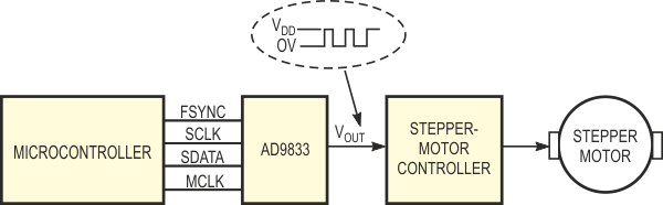
Figure 3 shows the complete system. The most significant bit of the on-chip DAC switches to the VOUT pin of the AD9833, thus generating the 0-to-VDD square wave that serves as the clock input to the stepper-motor controller. Writing to the frequency-control registers via a simple, three-wire interface sets the clock frequency. Writing a 0 to the frequency register stops the clock, thereby stopping the stepper motor. When you are not using the DAC, you can power it down by writing to a control register. This power-down action results in the AD9833's drawing only 2 mA from the supply. Reducing the MCLK frequency can further reduce the supply current. The AD9833 is available in a tiny, 10-lead package, so you can assemble the complete control system on a very small pc board.
 |
||
| Figure 3. | The complete stepper-motor controller uses a DDS IC to generate the variable frequencies for the circuit in Figure 1. |
|