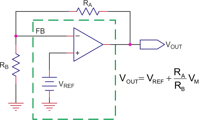
Controlling a power supply is a necessary task in many applications, such as in battery chargers, solar power controllers, and so on. Industry provides a rich number of off-the-shelf integrated power supplies that, unfortunately, do not offer a simple way to control the output. Usually a power supply can be schematized as a power operational amplifier with the non-inverting input connected to a reference voltage (in the green rectangle in Figure 1).
 |
||
| Figure 1. | This is a feedback-stabilized power supply scheme. | |
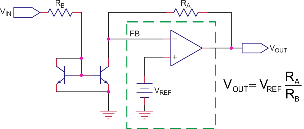
Typically, in power supply ICs (i.e. TI’s Simple Switcher) the only access you have to change VOUT is the inverting pin that controls the feedback (FB in Figure 1). A very easy method to control FB is to replace RB with a controllable current source, and the simplest and cheapest way to do that is using a current mirror (Figure 2).
 |
||
| Figure 2. | This voltage-controlled power supply uses a current mirror. | |
The precision you get from this design is tied to the precision of the current mirror you’ll use. If you decide for the Widlar basic two-transistor design, it’s important to rely on matched pairs built on purpose, like the BCV61; it’s easy to use such components in the better performing Wilson 4-transistors current mirror. The current mirror starts working only when VIN exceeds the VBE(on) of the mirror transistors, so there is a non-linearity at the beginning. All this is not very constraining if the suggested design is part of a loop where errors are compensated by the feedback magic.
 |
||
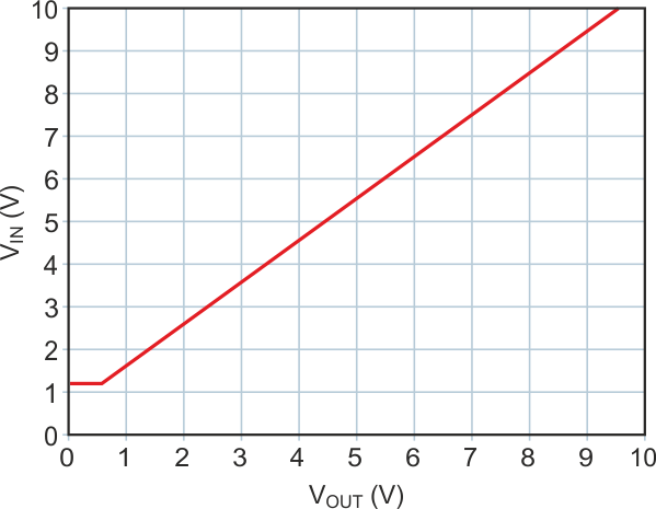
| Figure 3. | This diagram shows the PSpice simulated comportment of the circuit in Figure 2. |
|
The diagram in Figure 3 shows the PSpice simulated comportment of the Figure 2 circuit with VREF = 1.2 V when VIN spans from 0 to 10 V.
 |
||
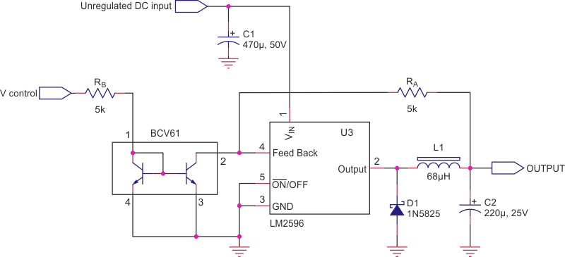
| Figure 4. | Here is a ‘designed-to-work’ application of the principle of Figure 2. | |
A straightforward implementation of the principle depicted in Figure 2 appears in Figure 4. Here, the well-known LM2596 is controlled by the off-the-shelf current mirror BCV61.
 |
||
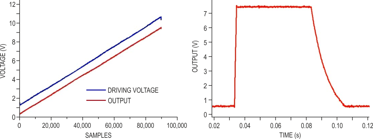
| Figure 5. | These test results for the circuit of Figure 4 show the driving voltage (blue track), and the output (red track on left). On the right, the response to a square wave shows a 1 ms rising time and a slow falling time tied to the output capacitor and the load resistor. |
|
The prototype of Figure 4 has been tested for linearity by connecting the unregulated DC input to a 22 V power supply, V control to a sawtooth generator spanning 0-10 V @ 5 Hz, and sampling the output (loaded with a 50 Ω resistor) with a scope. A pulse generator (0-8 V, 0.5 s) has been used to check the time response.
The results are shown in Figure 5. The circuit offers a good linearity (left) and a quite fast transient response for the rising time (roughly 1 ms to reach the settling point). The falling time is tied to the output capacitor (220 µF) and to the load (50 Ω during the test).