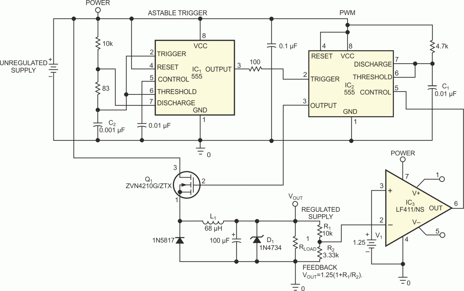
Most switch-mode power supplies rely on a PWM (pulse-width-modulated) output that is controlled via voltage feedback. A 555-timer IC can inexpensively perform PWM. The circuit in Figure 1 shows how to turn a 555 PWM circuit into an switch-mode power supply with only one simple equation. The design uses two 555s. IC1, in astable mode, triggers IC2 in PWM mode. IC1 is set to oscillate at approximately 60 kHz at a high duty cycle. The output is low for only approximately 2.5 µsec to trigger the PWM circuit and then goes high for the rest of the period. The PWM circuit has a maximum pulse width of approximately 85 µsec, and it becomes shorter, depending on the control voltage from the feedback circuit.
 |
||
| Figure 1. | Here’s one more use for the ubiquitous 555 timer: a switch-mode power supply. | |
You can reduce the chip count by using a 556 or another continuous-trigger source. The input must be (1.5VOUT+Margin), so for 5 V output you need 9 V minimum input. If you use CMOS chips and small timing capacitors C1 and C2, you can keep the operating current low. Thus, you can use a simple zener-diode regulator for the 555 and increase the input voltage to more than 30 V. The input-voltage limit is a function of how much power the zener supply can handle while delivering 5 to 10 mA to the 555s.
Q1 has low RDS(ON) and low VGS and can handle more than 40 V. D1 clamps any voltage spikes, such as those that occur when a large current flow ceases, causing a large magnetic field to be left in the inductor. You should select D1 according to the output voltage you need. For 5 V output, use a 5.6 V zener diode, for example. IC3, R1, R2, and V1 form the feedback circuit to set the output voltage. The output-voltage equation is
The TL431 is a popular part for setting a voltage reference and can easily create the 1.25 V shown for V1. You can supply 5 V at 1.5 A with an input of 9 to 40 V. At voltages higher than 12 V, you can add a 10 V zener-diode supply for the chips. The zener supply only slightly reduces the efficiency. With 12 V input, 5 V, 1.5 A output efficiency is approximately 70%, and it drops to 65% with a 40 V input and a zener circuit. The zener diode's influence is more noticeable at lower current levels; at a 50-mA load the efficiency drops to approximately 50%.