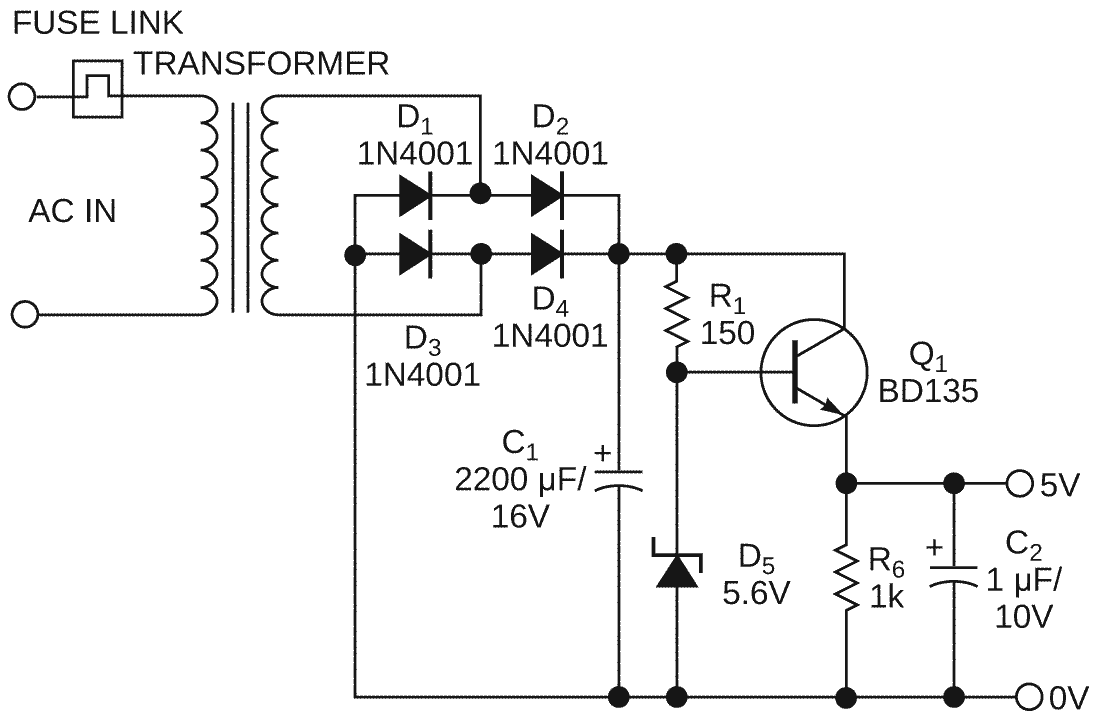
You can use simple circuits to implement small, regulated plug-in power supplies. In Figure 1, a basic and versatile 5 V supply uses a zener diode and an emitter-follower transistor. You must calculate and design the transformer such that Q1 is close to saturation at low mains voltages and nominal output current. Additionally, you must choose R1 to ensure proper bias for the zener diode. The transistor dissipates appreciable power when the mains voltage is high. Figure 2 shows that Q1 must handle nearly 0.75 W at nominal input voltage and output current. A TO-92 small-signal transistor, such as a BC337, is adequate for 300 mA, but a medium-power device, such as a BD135, is a better choice. To cut costs, this design uses no heat sink. Inasmuch as the circuitry is inside a nonventilated plug-in plastic case, the junction temperature of the BD135 attains temperatures greater than 100 °C.
 |
|
| Figure 1. | This simple plug-in power supply is effective but has no current limiting. |
Assuming that you need current limiting, if you use a linear current-limiting circuit, Q1 needs to dissipate nearly 2.5 W in the case of a short-circuited output. The probable result is the melting of the plastic case and the failure of Q1. To avoid that disaster, you can use switch-mode current limiting. Figure 3 shows the circuit of Figure 1 with some additional components, and Figure 2 shows the benefits of the limiting. Q1 and Q2 act as one emitter follower, but with lower base current. A small-signal Schottky diode, BAT85, which receives its bias from R3 and R2, provides an approximate 0.25 V reference voltage for comparator IC1A’s noninverting input. The inverting input reads the voltage drop created by the output current across R3. As long as the output current remains less than 300 mA, the output of the comparator is in a high-impedance state (open-collector), and the circuit works like a linear regulator.
 |
|
| Figure 2. | Without switch-mode current limiting, the circuit of Figure 1 can crash and burn. |
 |
|
| Figure 3. | The addition of a few components protects Figure 1’s circuit against overcurrent conditions. |
If the output current reaches 300 mA, the comparator's output switches low and thus turns off Q1 and Q2. The current through L1 decreases exponentially and flows through Schottky diode D1. As the emitter of Q1 is then at approximately 0.5 V, the bias current in D2 decreases. The voltage drop across D2 drops by approximately 10%. As a consequence, the output current decreases until it reaches 270 mA. Then, the comparator switches back to a high-impedance state, turning on Q1 and Q2 and again biasing D2 with R1 and R2. The current in L1 increases exponentially until it again reaches 300 mA. L1 is a 300-µH inductor using a powdered-iron core. Figure 4 illustrates the current-limiting action of the switch-mode circuitry.
 |
|
| Figure 4. | Switch-mode current limiting restricts current in Figure 3’s circuit to about 320 mA. |