Abhijeet Deshpande
Electronic Design
Harnessing solar energy directly to power a fan provides an environmentally friendly way of cooling or drying during the hot daylight hours of tropical environments. It also avoids the cost and complexity of storing the energy in batteries. Simply connecting the fan to a solar photovoltaic (PV) module, however, has a drawback.
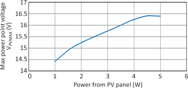
The voltage at which a PV module delivers its maximum power varies slightly with sunlight intensity voltage (Fig. 1). But the power – hence, the current – varies significantly. A static load near the panel’s maximum power capacity will pull the panel’s output voltage down well below its maximum power point when sunlight intensity drops, resulting in an inefficient utilization of the available energy.
 |
||
| Figure 1. | The maximum power a solar panel can produce and the voltage at which that occurs varies with sunlight intensity, making the panels inefficient when handling static loads. |
|
If the power level falls too far the fan will stop turning, and it will need a either a significant rise in power level or a mechanical “kick” to get started again. A dc-dc converter-based maximum power point tracker (MPPT) can ensure that the fan gets the most from the PV module regardless of the sunlight condition and keeps running (although at reduced speeds) even in very low light.
 |
||
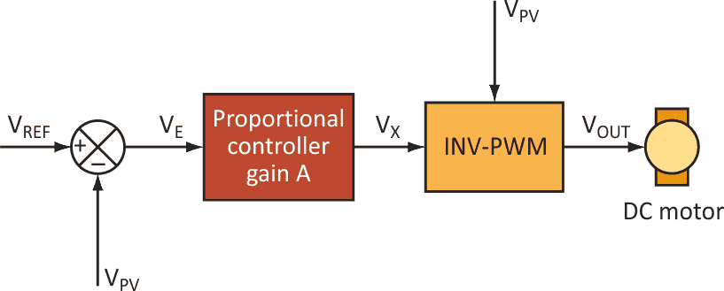
| Figure 2. | This circuit senses the solar panel’s output voltage and adjusts the load to raise the voltage until maximum power is obtained. |
|
Figure 2 illustrates the basic concept behind this design. An error voltage (VE), which is the difference between the PV panel’s output and a reference, drives a proportional controller (essentially a simple amplifier with gain A), producing an output voltage

The controller output drives an INV-PWM generator, which works opposite to a conventional pulse-width modulation (PWM) generator in that INV-PWM’s duty cycle decreases as the control voltage increases. The generator output drives the fan motor with an average voltage

Fan speed will vary with duty cycle, D, and duty cycle is controlled by VX.
Setting the reference voltage VREF to the PV panel’s maximum output voltage under full illumination allows this design to alter the load on the PV panel to always run at the maximum power point. With full illumination, then, VPV = VREF and VE = 0. Therefore, the controller output voltage VX is also zero, INV-PWM is operating at 100% duty cycle, and VOUT is at its maximum.
As sunlight intensity reduces, the PV panel’s power output declines and VPV drops. This drop causes the error voltage and hence VX to increase, reducing the generator’s duty cycle and thus the current draw from the PV panel. In effect, then, the circuit reduces the load that the panel sees.
If the reduction takes the load below the panel’s power capacity, VPV will start rising. As a result, the circuit will match the effective load to the panel’s maximum power point regardless of illumination level.
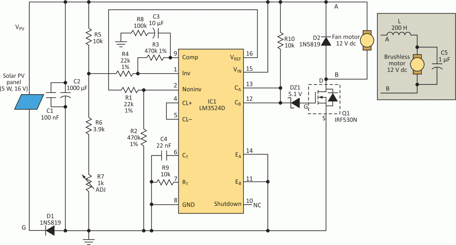
Figure 3 illustrates an implementation of this scheme. The design uses the Texas Instruments LM3524D regulating pulse-width modulator chip. In contrast to other regulator circuits that control the output voltage, this circuit regulates the input voltage. The solar panel connects to the circuit through diode D1 to prevent accidental reverse voltage. Capacitors C1 and C2 act as a filter for the switching circuit.
 |
||
| Figure 3. | A regulating pulse-width modulator chip that regulates the input voltage rather than the output voltage is the core of the maximum power tracker implementation. |
|
The modulator chip IC1 has a built-in error amplifier using pins 1, 2, and 9 and an internal 5-V reference at pin 16. The reference voltage feeds the divider circuit R1 and R2, which in turn drives the error amplifier’s non-inverting input. The panel voltage drives the amplifier’s inverting input through the voltage divider circuit R5, R6, and R7, with R7 a variable resistor set so the panel output is at VPVMAX under full illumination.
The values of resistors R1 through R4 give the error amplifier a gain of about 21. Resistor R8 and capacitor C3 form a compensation circuit with a time constant of one second to ensure the amplifier’s stability. Resistor R9 and capacitor C4 set the IC’s PWM switching frequency at 44.5 kHz.
The LM3524D PWM output uses two transistors driven 180° out of phase. This design uses them as a single-ended drive, connecting the transistors in parallel. The emitters connect to ground and the collectors drive the MOSFET Q1 so when the PWM transistors turn on, the MOSFET turns off. This creates the equivalent of an INV-PWM.
The connection to Q1 passes through a 5.1-V zener diode so the panel voltage must reach at least 8 V for Q1 to turn on. This ensures that under low light conditions the load is absent until the panel is able to build enough voltage to reliably start the circuit. A schottky diode (D2) connects across the 12-V dc motor to allow the stored energy in the motor inductor to freewheel through D2 when Q1 turns off.
With a conventional dc motor, the PWM waveform can feed the motor directly and the motor’s inductance will filter any current ripple so the motor operates smoothly. Many instrument cooling fans use a brushless dc motor, however, and these motors have built-in controller circuits. Such fans cannot accept pulsed voltage waveforms, so the converter output must be filtered as shown in the inset.
The filter consists of a 200-µH inductor (L) in series with the motor and a 1-µF polystyrene capacitor (C5) in parallel with the motor. The inductor consists of 20 turns of wire on a 10-mm E-type ferrite core or a torroidal core. The low-pass LC filter so formed has a cutoff frequency of about 11 kHz, which is much lower than the PWM frequency, so the motor simply sees a reduced voltage proportional to the duty cycle.
This MPPT circuit received extensive testing using both a dc fan and an instrument cooling fan. As the sunlight intensity changed, the fan speed varied. But even at very low solar intensities, the fan would run. The panel voltage closely tracked the maximum power point at all sunlight intensities.