EDN
Under certain conditions, ESD events can damage digital circuits by causing latch-up. For example, when ESD triggers them, parasitic transistors normally formed as parts of a CMOS device can behave as an SCR (silicon-controlled rectifier). Once ESD triggers, the SCR presents a low-resistance path between portions of the CMOS device and conducts heavily. Damage to the device can result unless you immediately remove power from the circuit. ESD from human interaction presents a significant problem for mobile industrial and medical devices. For adequate ESD protection, most medical and industrial devices require a grounded return path for ESD currents. In the real world, mobile devices may serve in environments in which properly grounded power outlets are unavailable.
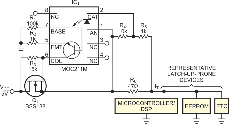
To protect expensive equipment from latch-up failures even when no ESD ground is present, you can add the power-interruption circuit shown in Figure 1 to prevent damage when ESD-induced latch-up occurs. Under normal conditions, current drawn by ESD-susceptible devices develops a small voltage across sense resistor R6. A voltage divider formed by R4 and R5 defines a reset-current threshold for the LED portion of optoisolator IC1, and, under normal operational current consumption, the LED remains dark.
 |
||
| Figure 1. | Upon sensing an overcurrent spike, this circuit interrupts power and enables the circuit's recovery from ESD-induced latch-up. |
|
The output of IC1 controls the gate bias applied to MOSFET Q1, which is normally on. When latch-up occurs, power-supply current drain rapidly increases by an order of magnitude or more. The large voltage drop developed across R6 forward-biases IC1’s LED, which in turn drives IC1’s phototransistor into conduction and shuts off Q1, interrupting dc power to ESD-susceptible devices for several milliseconds. In addition, the system's firmware design must allow for automatic recovery from a power interruption.
The following describes the relationship between the reset-current threshold and the values of R4 and R5:
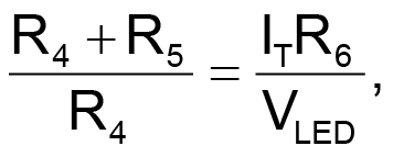
in which
VLED is LED voltage drop, and VCC > VLED.
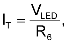
The ESD-induced fault threshold current, IT, is greater than or equal to the optoisolator LED's conducting forward-voltage drop divided by the value of sense resistor R6. Also, the raw power-supply voltage must exceed the LED's forward-voltage drop. Resistor R1 provides a path for IC1’s base-leakage current, and resistors R3 and R2 determine Q1’s gate-shutoff bias.
In Figure 1, the optoisolator presents an LED forward-voltage drop of 1.2 V. For the component values shown, the circuit momentarily interrupts VCC when ESD-induced power-supply current exceeds approximately 300 mA. Total cost of the six resistors, one MOSFET, and one optoisolator is approximately $1 (production quantities).