This Design Idea describes a single white-LED torch, which can be housed in an empty glue-stick tube and has a long rechargeable-battery life. The circuit is constructed with just a few commonly available parts. This torch has proven to be highly durable; the prototype model constructed by the author has been in service for nearly five years and is still in good working condition.
A single 1.2 V/ 2500-mAhr nickel-cadmium cell powers the torch (Figure 1). A simple transistorized boost switcher based on a tapped inductor is used to increase the voltage efficiently (up to approximately 80%) to the voltage needed for a typical white LED – in this case, about 3 V. Q1 and Q2 form an actable multivibrator producing rectangular waveforms at their collectors that are 180° out of phase.
 |
||
| Figure 1. | An inductive voltage booster powers the white LED. | |
Assume that at power-up, Q2 is off and Q1 is on. Under these conditions and with Q2 ’s collector high, Q3 is turned on via Q2 ’s collector resistor. With Q3 on, current flows through the first half of the inductor (from terminals 1 to 2).
At the end of this first half-cycle of operation, the multivibrator flips to the other state: Q2 turns on and Q1 turns off, and its collector goes high. Q3 is switched off; Q4 and Q5 are switched on via Q1 ’s collector resistor. The decaying inductor current now flows through terminals 1 and 3. Since L1-2 is equal to L2-3, and since they are on a common core, the inductance of L1-3 is four times that of L1-2 and L2-3. This increased inductance (and the corresponding additional turns on the core) leads to a reduction in the magnitude of the current but an increase in voltage across the LED. During this phase, current flows through the LED and, simultaneously, the 10-µF capacitor is charged. This phase lasts for a time period determined by the RC values in the actable circuit.
Once the RC time constant passes, the process repeats: Q1 turns on, Q2 turns off, and the other transistors switch as previously described. The current through terminals 1 and 2 of the coil again increases, storing energy from the battery in the inductor. During this phase, the 10-µF capacitor powers the LED.
 |
||
| Figure 2. | The circuit’s components can be assembled onto the two sides of a circular general-purpose board: Connections on the lower surface have been mirrored (a); from the top, component placement is shown in white, and connections are shown in green (b). |
|
Figure 2 shows how the circuit’s components can be assembled onto the two sides of a circular general-purpose board. Figure 3 shows how the torch could be assembled inside the glue-stick tube. Once the torch is assembled and powered up, adjust the 100-kΩ potentiometer in the actable circuit for maximum brightness. Note that, if needed, an additional transistor can be used in parallel with Q3 to boost the energy stored in the L1-2 inductor. The need is dictated by how quickly and deeply Q3 goes into saturation.
 |
||
| Figure 3. | The white-LED torch can be assembled inside an empty glue-stick tube. | |
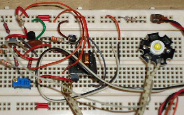
See photograph of the assembled circuit in Figure 4.
 |
||
| Figure 4. | Photo of the assembled circuit. | |