When using an optocoupler in a linear application, you should consider its gain drift with temperature. Traditional single- and dual-transistor-output devices have a notable gain drift with temperature. In recent years, some temperature-compensated optocouplers have appeared. However, another option is to use two optocouplers or a dual optocoupler with appropriate feedback to make the drift of one device cancel the drift of the other.
 |
||
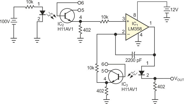
| Figure 1. | By using two optocouplers instead of one, you can cancel temperature-dependent gain drift. | |
The circuit in Figure 1 accomplishes that task by using a differential amplifier with the drift treated as a common-mode signal. In operation, it is interesting to apply a dc signal to the input and use digital voltmeters to simultaneously monitor the output of each optocoupler and the differential amplifier. Apply a heat gun and observe the individual outputs change rapidly while the amplifier output moves much more slowly. This result occurs even with optocouplers from different manufacturers. With optocouplers of the same type, you can observe good drift cancellation. Parts from the same manufacturer and dual devices give outstanding results. You can use individual optocouplers instead of dual devices to meet safety-agency spacing requirements.
 |
||
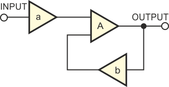
| Figure 2. | Control-system feedback theory explains the operation of the circuit in Figure 1. | |
To examine the method in control-system terms, consider Figure 2, which shows one amplifier, a, in the forward path and another amplifier, b, in the feedback path. Also consider the following equation:
where a/b is the ideal closed-loop gain and is multiplied by the loop-gain error term. Given that the error term is small (from the large gain A of the op amp), the gain of the system is seen as the ratio of the gains (current-transfer ratios) of the optocouplers.
You can also easily find this same ratio by setting the voltages to the op-amp inputs equal. The input and output signals for this analysis are currents, which precision resistors translate to voltages. The optocouplers in this design are not particularly fast devices, so the phase delays could cause oscillation without a feedback capacitor. You choose its value empirically by applying a pulse at the input and observing the rise time and overshoot at the output.