A few years ago, I worked at a disk-drive company. We had a plating facility that required square waves to drive the high-voltage plating operation. The challenge was that the square wave's pulse width had to be variable, along with the duty cycle. Also, the amplitude of the pulses had to be adjustable.
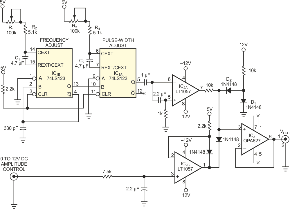
The circuit in Figure 1 satisfies all these criteria. The circuit delivers a unipolar (adjustable from 0 to 12 V) pulse with adjustable frequency and pulse width. The first half of a dual, retriggerable monostable multivibrator, IC1A, generates the frequency of the pulse train. The 100-kΩ potentiometer, R1, along with R2 and C1, sets the adjustable frequency. R3, R4, and C2 set the adjustable pulse width in the second section of the multivibrator, IC1B. The ac-coupled op amp, IC2A, running open-loop, delivers a ±12 V pulse output. D1 and D2 clamp the negative-going excursions of the pulse train to ground.
 |
||
| Figure 1. | This variable-frequency circuit allows amplitude modulation of its pulse-train output.. | |
The other half of the op amp, IC2B, serves as a level shifter that allows amplitude control over the range 0 to 12 V. You can modulate the amplitude at low frequency by varying the amplitude-control voltage.