Recently, my neighbor expressed a deep interest in building a low-power inverter from scratch. This portable power inverter takes the dc output from a low-voltage accumulator and creates a stable 230-VAC/50-Hz mains suitable for powering small items of equipment. As several inverter designs have already been published on the web, the goal here was to make the design easily accessible to others by using familiar and easily sourced components available to novices and hobbyists everywhere. Here is the design that uses readily obtainable N-type FETS and an inexpensive CMOS chip to generate the square wave signals. Because the square wave signals are generated by a single chip, it can easily be modified for 50 Hz or 60 Hz, either 115 V or 230 V, and a broad range of input voltages.
 |
| Figure 1. |
Schematic diagram of a portable power inverter. |
The circuit in Figure 1 is built around the monostable/astable multivibrator CD4047 (IC1). The resistor (R2) and capacitor (C3), connected to pins 2 and 3, will decide the frequency of the astable output pulses (here, it is at about 50 Hz). IC1 gives two similar frequency outputs at pins 10 and 11 (phase of the Q and /Q signals varies about 180 degrees). The square wave output signals are processed by the two-channel transistor banks (T1-T3-T5 and T2-T4-T6) to drive the power transformer (TR1). In my prototype, TR1 is a 60-VA toroidal transformer with a nominal 12-V rms secondary and 5-A current (Figure 2). I have powered up the inverter with an SMF battery of 12 V close to 7 Ah and successfully powered one 230-V/40-W lightbulb. The efficiency looks promising with neither the MOSFETs nor the transformer getting hotter than warm.
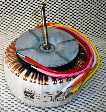 |
| Figure 2. |
The power transformer TR1. |
| |
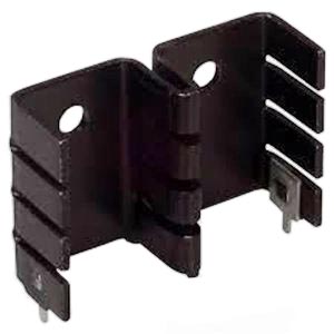 |
| Figure 3. |
The TO-220 heatsink for the T5-T6 MOSFETs. |
Because the inverter has fatal mains voltages present, it is highly recommended that it be put into a metal enclosure (with adequate vent holes). The largest component is the toroidal transformer, which should be securely mounted to the chassis. A proper (TO-220) heatsink should be used with the FETs (T5-T6), similar to the one shown in Figure 3. Note that both the upper and lower FETs can be bolted into a single (TO220x2) heatsink plate, provided that they are insulated from each other and from the heatsink plate. The proposed portable power inverter is intended to be used when there is no option to use ac mains for certain low-wattage devices (for example, as an in-car/camping inverter).
 |
| Figure 4. |
Astable mode waveforms. |
Materials on the topic
- Datasheet Texas Instruments CD4047B
- Datasheet ON Semiconductor BD139
- Datasheet Vishay BS170
- Datasheet Infineon IRFZ44N