A USB port offers a handy source of 5 V power for auxiliary devices. A USB port not only supplies power to a microcontroller and other essential circuitry, but also provides enough extra current head room to charge a small battery or supercapacitor energy-storage element. One typical approach to exploiting a USB port's leftover-current capability begins with an estimation of the essential circuitry's maximum current drain. You then place an appropriate current-limiting device in the path of the energy-storage device (Figure 1). Although easy to implement, this method doesn't use all of the current available from the USB port, and the energy-storage device slowly charges or recharges.
 |
|
| Figure 1. | In this typical method for drawing power from a USB port, the storage-element current is limited to a fixed value that is less than optimal. |
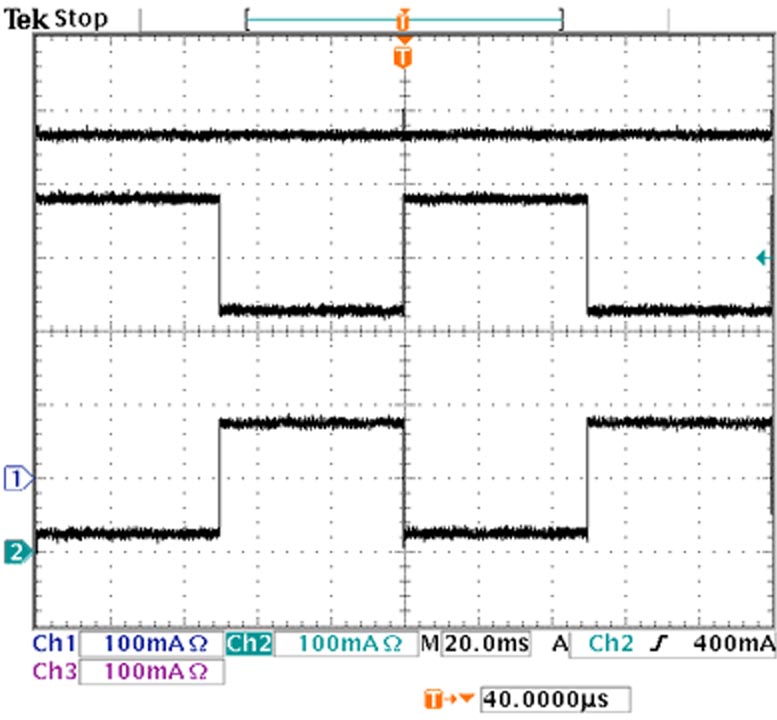
The circuit in Figure 2 uses all available USB power by dynamically adjusting the amount of current delivered to the energy-storage device and thereby siphoning a relatively constant and maximum current from the USB port. IC1, a Maxim MAX4173; IC2, a Maxim MAX6129; and the load-switch circuit comprising Q1, Q2, R2, and C4 form a control loop that limits the current flowing through Q1. The circuit maximizes current flowing to the energy-storage element (Figure 3) by ensuring that the sum of battery and essential-circuitry currents never exceeds the maximum of 500 mA for a high-power USB device. To reconfigure the circuit for low-power USB operation of 100 mA maximum, you can replace IC1 with a MAX4173HEUT, a device with 100 V/V gain, and R1 with a 0.25 Ω resistor.
 |
|
| Figure 2. | This circuit continuously monitors the total current drawn from the USB port and dynamically adjusts the storage-element current to avoid exceeding the port’s maximum output capability. |
 |
|
| Figure 3. | These waveforms taken from Figure 2 show that the sum of the essential circuitry current (middle trace) and storage-element current (bottom trace) never exceeds the 500 mA maximum that the USB port (top trace) specifies. |