Introduction
Familiar with the concept of hardware keylogging? A hardware keylogger is a perfect solution for monitoring user activity, at very low risk of disclosure. A hardware keylogger is a purely electronic device, so no access to the operating system is required, no traces are left, and software has no possibility of detecting such a device. However, the hardware keylogger concept inherits one weakness: physical access to the keylogger is required for retrieving captured data. This problem has finally found its solution: a Wireless Keylogger.
You should not use the Wireless Keylogger to intercept data you are not authorized to possess, especially passwords, banking data, confidential correspondence etc. Most countries recognize this as a crime.
The Wireless Keylogger consists of two main building blocks: the transmitter, and the receiver. The actual keylogging takes place in the transmitter, which is in fact a PS/2 hardware keylogger, with a built-in 2.4 GHz wireless module. Captured keystroke data is transmitted through the radio-link in real-time, rather than getting stored. The receiver on the other hand, is a wireless acquisition unit with a USB interface. All keystroke data received from the transmitter is sent to the host computer via USB. From the software side, this data is available through a virtual COM port, allowing any terminal client to be used for visualizing keystroke data.
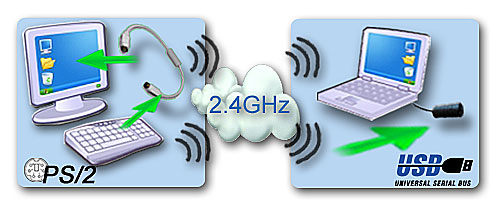 |
| Wireless Keylogger block scheme |
The entire system works in real-time, so text typed on the remote computer is seen immediately on the receiver side. The system has a maximum range of around 50 yards (meters). This corresponds to an effective range of around 20 yards (meters) through 2-4 walls, depending on their thickness.
 |
 |
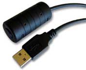
| Wireless Keylogger transmitter | Wireless Keylogger receiver |
Both the transmitter and the receiver are based on the same schematics and circuit board. Both have the same form factor, and are intended for mounting on PS/2 and USB extension cables. The recommended housing is an EMC-balun enclosure, which makes the device resemble a standard extension cable.
Components
The table below summarizes the BOM (Bill of Materials) contained in a single transmitter or receiver unit. An additional PS/2 extension cable is required for the transmitter, and a USB type A connector or cable is required for the receiver.
 |
 |
| Set of electronic components | Cables, enclosure, and PCBs |
Wireless Keylogger BOM
|
Designator |
Description |
Footprint |
Qty |
|
U1 |
Microcontroller AT91SAM7S64 |
TQFP64 |
1 |
|
U2 |
Transceiver nRF2401 |
QFN24 |
1 |
|
U3 |
Voltage regulator MCP1700T-330 |
SOT-23 |
1 |
|
Q1 |
Crystal 18.432 MHz |
HC-49 SMD |
1 |
|
Q2 |
Crystal 16 MHz |
HC-49 SMD |
1 |
|
R1, R2 |
Resistor 1.5 kΩ |
0805 |
2 |
|
R3, R4 |
Resistor 27 Ω |
0805 |
2 |
|
R5 |
Resistor 1 MΩ |
0805 |
1 |
|
R6 |
Resistor 22 kΩ |
0805 |
1 |
|
C1, C27 |
Capacitor 10 nF |
0805 |
2 |
|
C2, C28 |
Capacitor 1 nF |
0805 |
2 |
|
C3, C4, C6…C8 |
Capacitor 22 pF |
0805 |
5 |
|
C5 |
Capacitor 33 nF |
0805 |
1 |
|
C9 |
Capacitor 2.2 pF |
0805 |
1 |
|
C10, C11 |
Capacitor 1 pF |
0805 |
2 |
|
C12, C22,…C26, C32…C34, C42, C43 |
Capacitor 100 nF |
0805 |
11 |
|
C21, C31, C41 |
Capacitor 1 µF |
0805 |
3 |
|
L1 |
Ferrite Bead |
0805 |
1 |
|
L2 |
Inductor 3.6 nH |
0805 |
1 |
|
L3 |
Inductor 18 nH |
0805 |
1 |
Both the transmitter and the receiver use the same PCB and the same set of components (they differ by cabling and firmware). The Atmel AT91SAM7S64 microcontroller and the nRF2401 wireless transceiver are the core components. Both require crystals for proper operation. Besides the MCP1700 voltage regulator, all other components are passive (resistors, capacitors, and a few inductors). A simple wire is recommended for the dipole antenna. The double-sided two-layer PCB is shown on the pictures below.
 Click to enlarge |
 Click to enlarge |
| PCB layout - top side | Cables, enclosure, and PCBs |
If you feel skilled enough to manufacture PCBs yourself, you may use the 1:1 mask set available below. The reference design uses FR4 with 1.0 mm thickness.
 Click to enlarge |
 Click to enlarge |
| PCB mask - top side (PDF version, scale 1:1) |
PCB mask - bottom side (PDF version, scale 1:1) |
Assembly
The Wireless Keylogger electrical circuit is composed of two main building-blocks: the AT91SAM7S64 microcontroller and the nRF2401 transceiver. The accompanying passive components are mainly oscillator and RF circuitry. The entire circuit is powered with 3.3V, generated by the MCP1700 regulator and filtered by a set of capacitors. Power is drawn directly through the PS/2 bus (transmitter), or USB (receiver).
 Click to enlarge |
| Wireless Keylogger electrical schematics |
Use a fine tip for soldering (typically smaller than 0.5 mm) and soldering flux (for example RMA7). Don't overheat the components. Start the assembly with the nRF2401 transceiver, as it has the most difficult footprint. Proceed with the AT91SAM7S64 microcontroller and the MCP1700 voltage regulator. Always make sure pin 1 matches the first pad on the PCB. Finally, solder all the auxiliary circuitry: crystals, resistors, capacitors, and inductors. Leave the antenna for the end. You can use a dedicated ISM 2.4 GHz antenna, or simply make a quarter-wave dipole antenna from a piece of wire. The optimal length is 1.23" (3.125 cm). Assembled mini-boards should look similar to the ones on the pictures below.
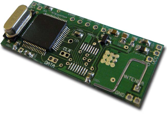 Click to enlarge |
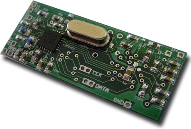 Click to enlarge |
| Assembled PCB top side with microcontroller | Assembled PCB bottom side with transceiver |
After assembling the circuit boards, it's time for the cabling. Apart from firmware, this is the place where the transmitter differs from the receiver. The transmitter should be coupled in parallel with the PS/2 bus. The PCB has pads for connections leading both to the computer, and to the keyboard. The receiver, on the other hand, should have a standard connection to the USB port. The images below show how the connections should be made.
 Click to enlarge |
 Click to enlarge |
| Transmitter PS/2 wiring diagram | Receiver USB wiring diagram |
Use PS/2 and USB extension cables, cut them open, and isolate the signal lines. The tricky part is to identify how the wires inside correspond to signal lines. Some PS/2 and USB cables have standardized colors, however trusting in this is very risky. The recommended solution would be to use a short-circuit tester or ohmmeter to find out which wire corresponds to which signal. The diagrams below will be helpful.
PS/2 plug pinout (transmitter unit)
|
Signal |
Description |
PS/2 pin |
Comments |
|
VCC |
+5V power |
4 |
must be connected to module |
|
GND |
Power ground |
3 |
|
|
CLK |
Clock |
5 |
|
|
DATA |
Data |
1 |
|
|
NC |
Unused lines |
2, 6 |
not used by module if present, leave in original state |
|
SHLD |
Shield |
— |
 |
 |
USB plug pinout (receiver unit)
|
Signal |
Description |
USB pin |
Comments |
|
VCC |
+5V power |
1 |
must be connected to module |
|
D- |
Data |
2 |
|
|
D+ |
Data |
3 |
|
|
GND |
Power ground |
4 |
|
|
SHLD |
Shield |
— |
not used by module if present, |
 |
 |
If the microcontrollers you're using aren't programmed yet, this is a good moment to upload firmware using the ISP (In-System Programming) technology. Read the firmware section to get more details. When this is done, the mini-boards should look similar to the ones on the pictures below.
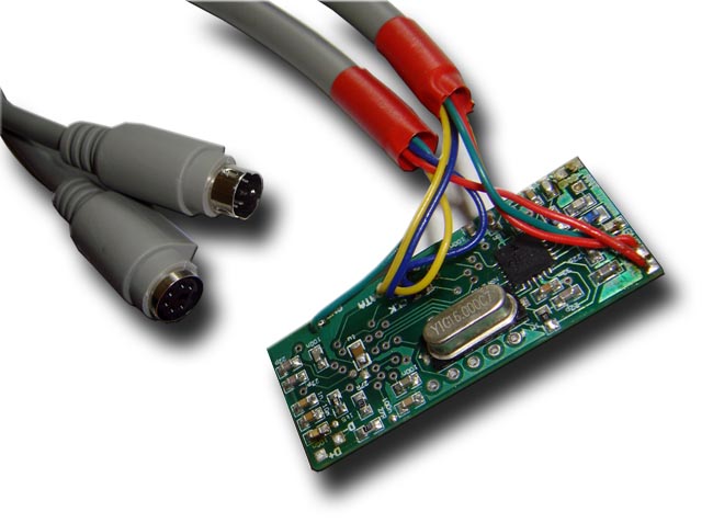 Click to enlarge |
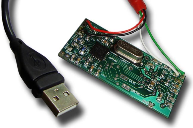 Click to enlarge |
| Transmitter circuit board wired to PS/2 bus | Receiver circuit board wired to USB |
Before putting the enclosure on, we recommend to do one last check. Use a short-circuit tester or ohmmeter to check the resistance between the power supply (VCC) and ground (GND) on the USB and PS/2 connector. The presence of a short circuit here means, that the whole circuit should be revised, otherwise it could lead to damaging your computer. If everything's OK, mount the enclosure using glue or resin, and you're set to go.
To be continued