Power-up
Once you have a transmitter-receiver pair of devices assembled, it's time for the first test. We recommend to use a single computer for testing both devices. First, power down the computer and connect the transmitter unit between the PS/2 keyboard and PS/2 port.
 |
 |
| Connect the transmitter unit to the PS/2 port | Connect the PS/2 keyboard to the transmitter unit |
When done, boot the computer and make sure the PS/2 keyboard is working properly (no influence of the keylogger should be noticeable). Now it's time to test the receiver unit. Before you proceed, please download the KeeLog driver files first. Unzip and save the files to the local hard disk on your computer. Then, plug the receiver unit into a free USB port (no need to power down the computer). Make sure it's in a position enabling reception of the radio signals coming from the transmitter.
 |
| Connect the receiver unit to a free USB port |
The first time the receiver unit is connected, a driver installation dialog will appear. Strictly speaking, it will use the bundled virtual COM port driver delivered with most operating systems, such as. However, the corresponding INF description file has to be selected manually. When the system asks for a driver, browse to the location where the driver file was saved. The pictures below illustrate the process.
 Click to enlarge |
 Click to enlarge |
| Choose to locate and install driver software | Choose to browse for driver |
 Click to enlarge |
 Click to enlarge |
| Choose to show browse option | Browse to driver location |
If the driver installation process was successful, the receiver unit should be visible as a USB to serial converter. Open the Device Manager in Windows to find out, and check which virtual port was assigned to the device.
 |
| Receiver unit visible in the Device Manager |
To start receiving keystroke data from the transmitter unit, you may use any terminal client, such as Hyperterminal. We recommend to use our free Simple Serial Monitor application for it's flexibility and ease of use.
 |
| Simple Serial Monitor (free terminal client from KeeLog) |
After launching Simple Serial Monitor (or any alternative application), remember to set the correct COM port. If everything proceeded correctly, the receiver unit will immediately show all keystrokes typed on the PS/2 keyboard.
 |
|
| Remote computer with PS/2 transmitter unit | Local computer with USB receiver unit |
The next step would be to test the same using two different computers. Make sure they are in transmission range. If you see text popping up in the terminal window, then your Wireless Keylogger set is ready for it's first real mission. Remember to use this device only for legitimate purposes!
Download
|
Microcontroller firmware for programming the transmitter and receiver |
|
|
Driver allowing the receiver to be recognized as a virtual COM port |
|
|
Free software for displaying intercepted keystroke data through the virtual COM port (equivalent to Hyperterminal). Requires the Microsoft .NET Framework. |
|
|
Software for flashing firmware using the SAM-BA bootloader |
|
|
Tutorial on flashing the firmware into the microcontroller through a built-in bootloader, without using any additional programmer |
Firmware
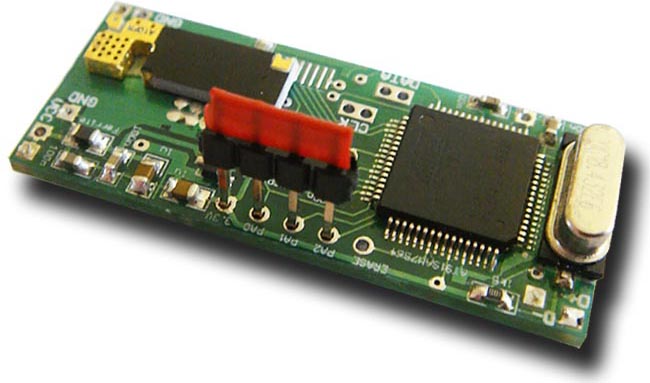
Modern microcontrollers, such as the Atmel AT91SAM7S64 have highly-packed footprints, making it difficult to find traditional programmers supporting them. That's why ISP (In-System Programming) has developed very rapidly in the recent years. ISP allows for assemble the entire circuit board first, and then flash the firmware, often using very simple tools. The AT91SAM7S64 implements a very convenient ISP solution, based on the built-in USB module. It's called the SAM-BA (SAM Boot Assistant), and requires only a USB cable and a few simple jumpers. To run SAM-BA on your Wireless Keylogger mini-boards, first download the AT91 ISP tool. Then, follow the steps below to complete firmware flashing on the transmitter and receiver unit.
Step 1: Applies for the transmitter unit only. Prepare a USB cable with a type A male plug on one side, and isolated wires on the other side. Solder the USB lines VCC, GND, D+, and D- to the appropriate pads on the PCB. This step is not necessary for the receiver, as it already has a USB connection.
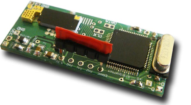
Step 2: Prepare a few short wires for short-circuiting the SAM-BA pins: TST, ERASE, PA2, PA1, PA0, 3.3V. Solder one end of each wire to the SAM-BA pads on both boards. Alternatively, you may prepare special jumpers as seen on the pictures.
 |
| SAM-BA wiring scheme (PDF version) |
Step 3: Install the AT91 ISP software package.
Step 4: Connect the device to a free USB port. A Device Not Recognized message is normal at this stage.
Step 5: Short the ERASE and 3.3V signal wires for a moment. This will erase the microcontroller's flash memory.
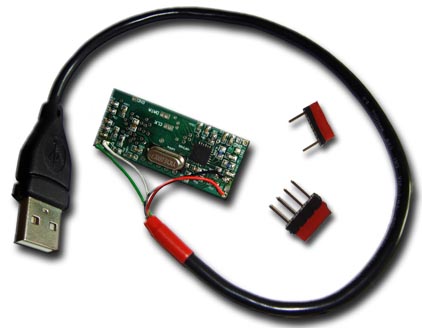 |
| USB cable and jumpers for SAM-BA bootloading |
 Click to enlarge |
 Click to enlarge |
|
Memory erasing |
Bootloader activation (PA0, PA1, PA2 and TST shorted to 3.3V) |
Step 6: Disconnect the device from the USB port. Make sure the ERASE pin is not connected to 3.3V any more. Now short the set of pins PA0, PA1, PA2 and TST to 3.3V. Connect the device to the USB port again (Device Not Recognized may appear again). Leave the device connected for approximately 10 seconds, and then disconnect the device from the USB port. This operation should have activated the SAM-BA bootloader.
Step 7: Remove all shorts or jumpers and connect the device to the USB port. The New Hardware Found dialog should appear. Please follow the default procedure and allow the wizard to find the drivers itself.
 |
| Found New Hardware wizard |
Step 8: Open the Device Manager and verify that the SAM-BA bootloader has been activated.
 |
| Device Manager with Atmel AT91 device |
Step 9: Run the SAM-BA application from the AT91 ISP software suite and select the AT91SAM7S64-EK target microcontroller board.
 |
| Microcontroller board selection |
Step 10: After establishing the connection with the board, switch to the Flash tab, select the appropriate firmware for the transmitter/receiver, and click on Send File. When the application asks whether to lock and unlock the involved flash regions, select yes. If you were successful in finalizing this step, it means the firmware has been downloaded to the microcontroller.
 |
| SAM-BA Main Window |
Remember to go through the SAM-BA procedure for both the transmitter, and the receiver. When finished, both devices are ready to go.