Designers often choose a super-regenerative receiver – despite its frequency instability and poor selectivity – for battery-powered, short-range, wireless applications in which power consumption is a major issue. Examples include remote-keyless-access systems, automobile alarms, biomedical monitors, sensor networks, and computer peripherals. A super-regenerative detector can also demodulate frequency-modulated signals through slope detection. Tune the detector so that the signal falls on the slope of the detector circuit's selectivity curve. This Design Idea presents a super-regenerative receiver that consumes less than 1 mW and operates in the license-free, 433-MHz ISM (industrial/scientific/medical) band.
In its simplest form, a super-regenerative receiver comprises an RF oscillator that a “quench signal,” or lower frequency waveform, periodically switches on and off. When the quench signal switches on the oscillator, oscillations start to build up with an exponentially growing envelope. Applying an external signal at the oscillator's nominal frequency speeds the growth of the envelope of these oscillations. Thus, the duty cycle of the quenched oscillator's amplitude changes in proportion to the amplitude of the applied RF signal (Figure 1).
 |
|
| Figure 1. | In a super-regenerative detector, the arrival of a signal starts RF oscillations sooner than under no-signal conditions. |
A super-regenerative detector can receive AM signals and is well-suited for detecting OOK (on/off-keyed) data signals. The super-regenerative detector constitutes a sampled-data system; that is, each quench period samples and amplifies the RF signal. To accurately reconstruct the original modulation, the quench generator must operate at a frequency a few times higher than the highest frequency in the original modulating signal. Adding an envelope detector followed by a lowpass filter improves AM demodulation (Reference 1).
Figure 2 is a block diagram of the super-regenerative receiver circuit in Figure 3. The heart of the receiver comprises an ordinary Colpitts-configured LC oscillator operating at a frequency that the series resonance of L1, L2, C1, C2, and C3 determines. Switching off transistor Q1’s bias current quenches the oscillator. (Note that increasing C1 and C2 improves the oscillator's frequency stability at the expense of increased power consumption.) Cascode-connected transistors Q2 and Q3 form an antenna amplifier that improves the receiver's noise figure and provides some RF isolation between the oscillator and the antenna. To conserve power, the amplifier operates only during oscillation growth.
 |
|
| Figure 2. | The super-regenerative receiver is considerably simpler than a superheterodyne circuit. |
Based on a Schmitt-trigger circuit, the quench generator switches the oscillator and RF-amplifier stage. To improve sensitivity, the triangular waveform across C5 quenches the oscillator, and the square wave at the output of IC1 switches the RF amplifier. The quench generator's two outputs are phased in quadrature so that the RF amplifier has received power when the detector's oscillations start to grow. The quench frequency of this circuit is 100 kHz to allow data transfers at rates as high as 20 kbps.
The envelope detector comprises a common-source amplifier that's nominally biased to operate in Class B mode. To increase this stage's gain, you apply a small amount of bias current to make it operate in Class AB mode. To reduce the load on the oscillator's LC tank circuit, C10 connects to a tap on inductor L1, as inductor L2 shows.
 |
|
| Figure 3. | The super-regenerative receiver features relatively few components. |
The first stage in the data-recovery circuit comprises buffer IC2A; amplifier IC2B; and a third-order, lowpass filter for suppressing quench-frequency components in the envelope detector's output. A dc-coupled Schmitt-trigger circuit, IC3, extracts the transmitted data from the demodulated signal. A lowpass filter comprising C12 and R16 extracts the demodulated signal's dc component and sets the Schmitt trigger's decision threshold. As a consequence, the data transmitter must use a dc-balanced coding scheme, such as Manchester coding, for modulation. On the receiving end, no additional active components are necessary for extracting the data-recovery circuit's decision threshold, which helps minimize the receiver's power consumption.
 |
|
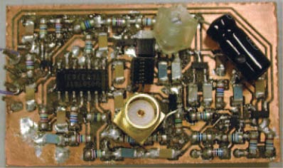
| Figure 4. | A prototype version of a super-regenerative receiver uses mostly surface-mount components. The large, black, leaded component in the upper right corner is a power-supply-decoupling capacitor. Note the RF-input connector in the center of the pc board. |
The prototype occupies a compact pc board measuring approximately 5×3 cm (Figure 4). Using a simple, homemade PRBS (pseudorandom-binary-sequence) generator that uses Manchester coding with a 28–1-bit sequence (Reference 2), BER (bit-error-rate) measurements yield the results in Figure 5. These results demonstrate a sensitivity of less than –100 dBm for a 10–4 BER at 1 kbps. The receiver consumes 270 µA at 3 V for a power consumption of 810 µW. As a further enhancement to the design, it includes a transmitter circuit based on Maxim's MAX1472, creating a simple, compact, low-cost, and low-power transceiver for the 433-MHz ISM band. You can easily adapt the receiver circuit for recovery of AM audio or other analog signals by replacing the Schmitt trigger, IC3, with a conventional audio-output amplifier. Retune the RF oscillator to cover the frequency range of interest.
 |
|
| Figure 5. | Measurements of bit-error rate versus input RF power highlight the prototype receiver's sensitivity. The frequency is 433.92 MHz. |
References
- Insam, Eddie, “Designing Super-Regenerative Receivers,” Electronics World, April 2002, pg 46.
- Mélange, Cedric, Johan Bauwelinck, Jo Pletinckx, and Jan Vandewege, “Low-cost BER tester measures errors in low-data-rate applications,” EDN, Dec 5, 2005, pg 123.