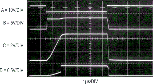
Figure 1, fast rise time pulse generator, switches a high grade, commercially produced tunnel diode mount to produce a 20 ps rise time pulse. O1’s clocking (trace A, Figure 2) causes Q1’s collector (trace B) to switch the capacitively loaded Q2-Q3 current source. The resultant repetitive ramp at Q3’s collector (trace C), buffered by Q4, biases the tunnel diode mount via the output resistors. The tunnel diode driven output (trace D) follows the ramp until abruptly rising (trace D, just prior to 4th vertical division). This departure is caused by tunnel diode triggering. The edge associated with this triggering is extremely steep, with a specified rise time of 20 ps and clean settling.
 |
|
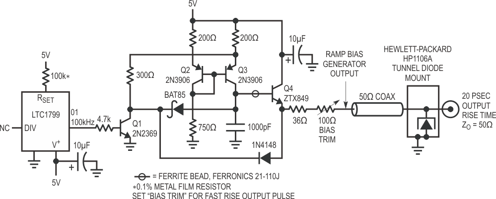
| Figure 1. | Current ramps into tunnel diode until switching occurs, producing a 20 ps edge. Q1, squarewave clocked from O1, switches Q2-Q3 capacitively loaded current source, producing repetitive ramps at Q4. Ascending current through output resistors triggers tunnel diode. |
 |
|
| Figure 2. | O1 (trace A) clocks Q1’s collector (trace B), switching capacitively loaded Q2-Q3 current source. Resultant repetitive ramp at Q3’s collector (trace C), buffered by Q4, biases tunnel diode via output resistors. Tunnel diode output (trace D) follows ramp until abruptly triggering. |
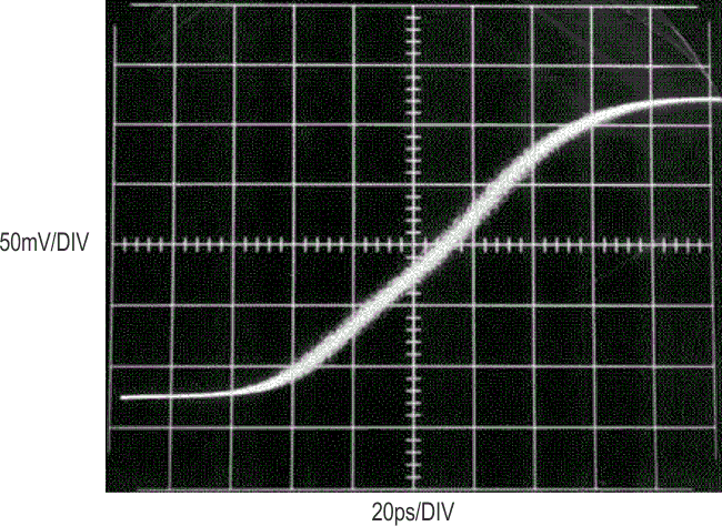
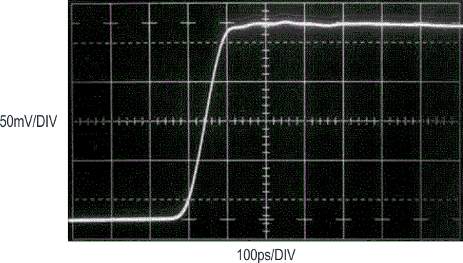
Figure 3 examines this edge within the limitations of a 3.9 GHz (tRISE = 90 ps) sampling oscilloscope. The trace shows the tunnel diode’s switching, driving the oscilloscope to its 90 ps rise time limit. Figure 4, slowing sweep speed to 100 ps/divison, shows pulse top settling (in a 3.9 GHz bandwidth) within 4% inside 100 ps.
 |
|
| Figure 3. | Figure 1’s 20 ps edge drives a 3.9 GHz sampling ‘scope to its 90 ps rise time limit. Trace granularity is characteristic of sampling oscilloscope display. |
 |
|
| Figure 4. | Reducing sweep speed shows 4% pulse top flatness within oscilloscope’s 3.9 GHz (tRISE = 90 ps) bandwidth. |