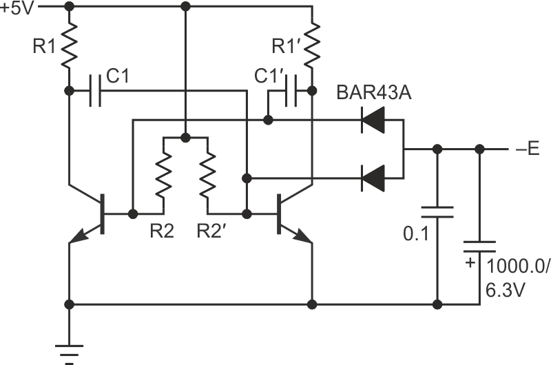
While choosing an op-amp buffer, some sources of negative supply were considered, because the buffer op-amp had to provide true zero voltage on its output. In reality, a typical rail-to-rail output op-amp isn’t capable of this, it can guarantee at least several mV on its output, while its host – a high-resolution DAC, for example – may have resolution in µV range. My application required a true zero output, hence the problem.
I definitely needed some negative supply to increase the “footroom” around zero. (Not “headroom” because here we are dealing not with the upper, positive supply, but with the lower one.) While exploring alternatives, the idea arose to use a photocell instead of any ordinary voltage converter. It resulted in this circuit (Reference 1).
But while this solution can boast its very low output noise, its output power is somewhat restricted. By the way, the best output I was able to get with this “photocell” is more than 0.81 V at RLOAD = 2k and 2 × 5 = 10 mA of total current through LEDs (super bright of OSRAM).
This was quite enough for my application, but it was difficult for me to stop right away, so the circuit in Figure 1 was born. Both these circuits can be used when a simple local low-noise negative supply of low voltage is required.
 |
|
| Figure 1. | A second circuit to accomplish a true zero output of an op-amp that is based on a symmetrical multivibrator for better efficiency than the previous photocell design idea. |
This second circuit is based on a symmetrical multivibrator and has far better efficiency than its “photocell” sibling, but its output noise is somewhat higher. So, it may be more ideal for power-restricted applications.
Dual Schottky BAR43A performs like a full-wave rectifier, its symmetry reduces the level of the multivibrator frequency in the output noise. The same can be said about the symmetry of the multivibrator itself. Like its older sibling, the circuit is utterly tolerant to output shorts because both are current sources.
One point about the transistors: almost all current NPN BJTs have a low VEBO of about 5…7 V. This parameter is important for the BJTs of a symmetrical multivibrator. A good choice for a 5 V powered circuit would be any transistor with maximal VEBO of at least 6 V, for example the BC547, 2N5551, MPS2222A, etc.
Now, it is hard to find something like the 2SC3616 (NEC) with a VEBO that stands around 15 V (and h21 > 2000 by the way) so, if you want to adapt the circuit to higher voltages, you have to use MOSFETs with a maximum gate-to-source voltage of about 20 V.
The components’ values are: R1 = R1′ = 5.6 k, R2 = R2′ = 30 k, C1 = C1′ = 0.1 µF. The output capacitors should be of low impedance.
The frequency here cannot be calculated using the known formulas for a symmetrical multivibrator; obviously it would be higher. With the components shown as well as the 910 Ω load, the frequency is approximately 2 × 0.65 = 1.3 kHz.
The circuit consumes less than 1.5 mA from +5 V and produces –0.3 V on a 910 Ω load.
Reference
- Demchenko, Peter. "Photocell makes true-zero output of the op-amp."