Testing the system
Testing was done at various sunlight intensities. For any given sunlight intensity, VPV, IPV, VM, IM, etc., are measured. Figure 5 shows the variation of PV power (PPVON), converter power (PM), and total power (PTOT) with the converter ON.
 |
|
| Figure 5. | Plots of PV power, converter power, and total power with the converter turned ON at 52 V are provided. |
Note that at VPV = 51.5, the maximum power drawn from the converter is about 22 W. This is just an initial setting. If required, it can be increased by boosting the converter output voltage. As we move toward higher VPV voltage, the total power goes up somewhat due to more power coming from the PV.
When readings were taken for the converter in Figure 5, at the same time and at the same sunlight intensity (in quick succession), another set of readings were taken with the converter OFF. To study the behavior of the PV array, PPVON and PPVOFF were plotted in Figure 6.
 |
|
| Figure 6. | This PV power plot shows when the converter is OFF and when the converter is turned back ON. |
Note that when the converter is turned ON, the variation in VPV is restricted to a narrow range from 51.5 to 52.8 V. When the converter is turned OFF, the VPV range is much wider, from 45.4 to 52.8 V. PPVOFF is plotted with its corresponding VPV range of 45.4 to 52.8 V. The PPVON plot from Figure 5 is replotted in Figure 6, against the VPV range of 45.4 to 52.8 V, for the sake of comparison only.
The plots clearly reveal that when the converter is OFF, PV power is slightly higher. As discussed earlier, the SDL itself follows maximum power point. Hence, when we turn the converter ON, maximum power point gets disturbed due to a change in VPV. Therefore, about a 1-W reduction in power output from the PV panels is observed when the converter is turned ON.
Resistive load testing
Lamps L1, L2 and L3 in Figure 3 were replaced with three 265-Ω resistors. The resistive loads don’t track the maximum power point. However, when the converter is turned ON, the operating point of the PV panels moves nearer to the maximum power point.
It was observed that with the converter ON, we get an extra 10% to 15% PV power output. Thus, if the proposed circuit is used for loads that don’t track maximum power point, we get some extra power from the PV.
Component selection
The proposed circuit uses just diodes and resistors (instead of complex switching power circuits) to control power coming from mains supply. It’s necessary to minimize losses in these components.
Even though current in each of the diodes is less than 1 A, a high-current-rated diode type 6A10 has been selected. These 6-A diodes have lower forward voltage at lower currents. A Schottky diode will have much smaller forward voltage. However, Schottky diodes aren’t available in high peak-inverse-voltage (PIV) ratings. The diode 6A10 has a PIV of 1,000 V. The AC-DC converter is connected to a mains supply; from there, high-voltage transients can enter the circuit. Hence, use of high PIV diodes is recommended.
If the forward voltage drop of the selected diode isn’t acceptable, then a MOSFET-based polarity reversal protection circuit can be used. Such circuits have negligible forward voltage drop.
Moreover, on the PV side, during lightning, high-voltage transients may enter the circuit. Usually, solar panels come with built-in transient voltage protection. It’s recommended to have a 100-V TVS diode DT across the output terminals of the PV array on the panel. An electrolytic capacitor of 4,700 µF/ 100 V is connected at the output of PV array. This will smooth out sudden variations in PV voltage.
Checking out standby mode
On a sunny day, if there’s steady and sufficient light output from the SDL itself, then the user can manually turn OFF the AC-DC converter to save power. However, if the sunlight is changing throughout the day, then the AC-DC converter must always be kept ON.
Even on partially cloudy days, there are intermittent spells of bright sunshine. Under such conditions, it’s possible to put the AC-DC converter in Standby Mode. By putting the converter in Standby mode, current drawn will be negligibly small. Whenever the sunlight intensity reduces, the converter will instantaneously come out of standby mode and provide sufficient light from mains power.
In Figure 3, components shown with * marks are employed to generate the Standby signal. Current-sensing resistor RSH is used to sense the PV current. When PV current exceeds a threshold value (user-settable), the Standby signal (comparator output) goes high. This signal is connected to the converter, which then goes into Standby Mode. Components RZ (3.3 kΩ, 2 W) and DZ (Zener 5.1 V, 1 W) are used to generate the 5-V power supply (VZ) for the comparator.
Figure 7 shows the circuit diagram of the comparator. It consists of comparator IC1 (LM311). The reference voltage is connected to the inverting terminal Pin 3 using R10, R11 and R12. This reference voltage is user-settable with the help of potentiometer R10. Pin 3 also gets current from resistor R13, which is controlled by PNP transistor T1 (BC556). The non-inverting terminal Pin 2 is connected to the current-sensing resistor RSH.
 |
|
| Figure 7. | The comparator circuit with hysteresis generates the Standby signal. |
When the drop across RSH exceeds reference voltage at Pin 3, the Standby signal goes high. In addition, T1 turns OFF and the reference voltage drops, thus introducing hysteresis. The T1 and R13 circuit is required because, in this case, the current signal must be connected to the non-inverting terminal. Therefore, this terminal can’t be used to introduce hysteresis, as is usually the case.
Figure 8 shows the capture of PV current (yellow) and Standby signal (blue). A 50-mV hysteresis is generated, which translates to about 106 mA of PV current. When the Standby signal is high, it will not become low unless the PV current reduces by 106 mA. This will diminish the unwanted chattering of the Standby signal.
 |
|
| Figure 8. | Standby signal: yellow trace – PV current 106 mA/div; blue trace – Standby signal 2 V/div., hysteresis 50 mV (106 mA). |
Construction of the system
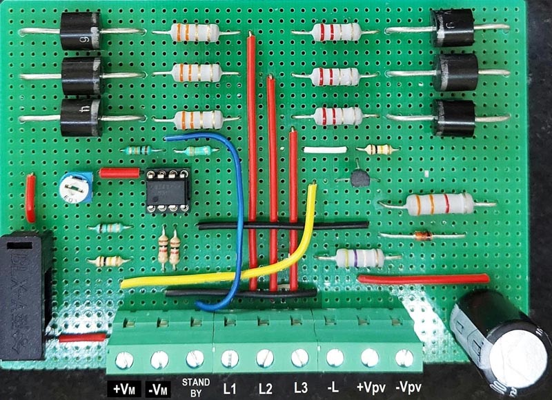
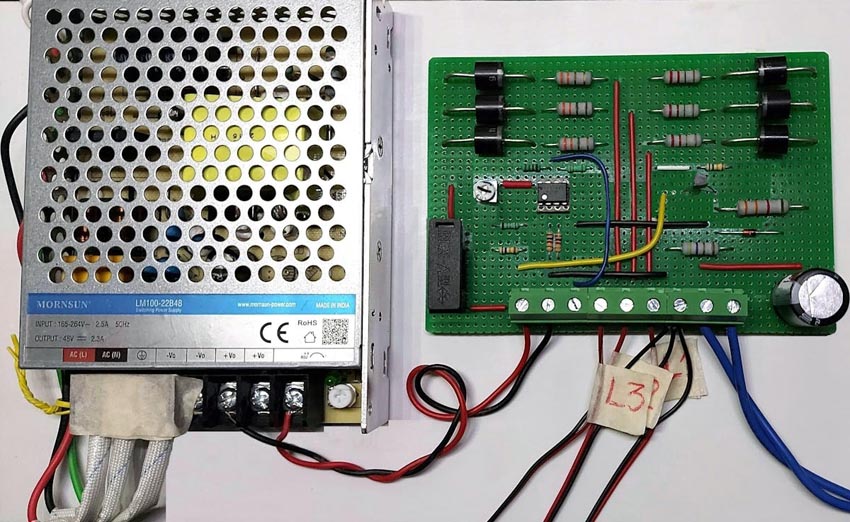
Figure 9 shows the assembled PCB as per the circuit diagram in Figure 3. It includes the PV-Pushback circuit as well as the Standby signal generator circuit. Interconnections to this PCB are available on the 9-pin terminal strip. The power supply from the converter is connected through a fuse for safety.
 |
|
| Figure 9. | This is the assembled PCB for a lighting system based on the PV-pushback-effect. |
In Figure 10, the PCB and the AC-DC converter are mounted on same baseplate.
 |
|
| Figure 10. | In this circuit, the AC-DC converter is mounted on a single board. |
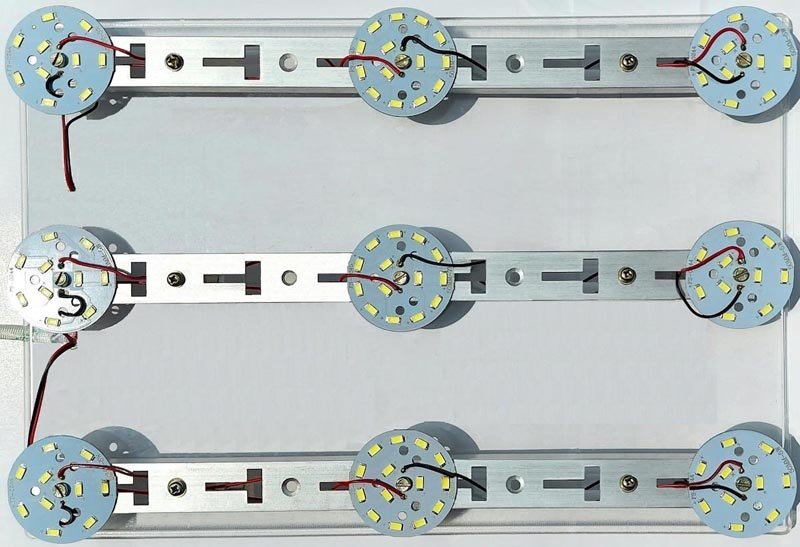
Figure 11 shows the lamps L1, L2 and L3 mounted on a baseplate. Each lamp is made using three metal-core PCBs having white LEDs. Two round PCBs have five LEDs each and the middle round PCB has seven LEDs. Overall, each lamp has 17 LEDs.
 |
|
| Figure 11. | Three LED lamps are used in the demonstration. Each lamp has 17 white LEDs. |
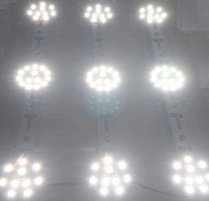
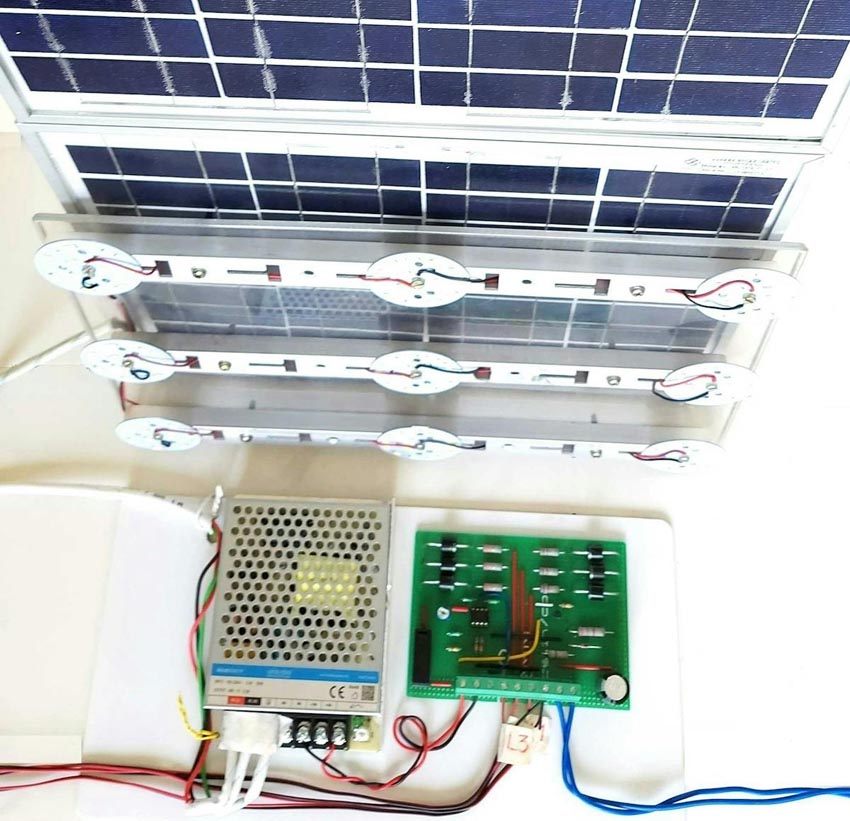
Figure 12 illustrates the lamps turned ON, and Figure 13 shows the complete system.
 |
|
| Figure 12. | Lamps L1, L2, and L3 provide constant light output using the PV-pushback-effect. |
 |
|
| Figure 13. | This photo shows the complete system. |
Conclusions
All PV panels demonstrate the pushback effect. This effect can be used to mix DC power coming from another source such as a converter or a battery etc. In this article, one example of LED lamp load is presented, but we can extend this to other types of loads, such as heater loads, fan loads, mobile and small two-wheeler chargers, etc. It eliminates all of the drawbacks of pure solar PV systems.
Even though we’re using a backup supply, the power drawn will be optimized based on the sunlight conditions. Users will not notice the transition from daytime to nighttime. It also offers users the opportunity to turn OFF the backup supply if it’s a sunny day. On days with varying sunlight conditions, we can automatically put the converter in Standby mode to save power in converter.
Office buildings, homes, hotels, etc., should have a few of these types of systems. They will save power and work as emergency lamps in the daytime during power failures. If a battery-based system is designed, then it can provide light during nighttime, too, if the grid has failed.
To summarize, a very simple, low-cost lighting system is proposed that doesn’t use any complex switching circuits. It offers reliable day and night operation without user intervention, while providing maximum utilization of solar energy in all seasons. It will prove useful for variety of loads.