There’s been interest recently here in the land of Design Ideas (DIs) in a family of simple interface circuits for pulse width modulation (PWM) control of generic voltage regulators (both linear and switching). Members of the family rely on the regulator’s internal voltage reference and a discrete FET connected in series with the regulator’s programming voltage divider.
PWM uses the FET as a switch to modulate the bottom resistor (R1) of the divider, so that the 0 to 100% PWM duty factor (D) varies the time-averaged effective conductance of R1 from 0 to 100% of its nominal value. This variation programs the regulator output from VO = VS (its feedback pin reference voltage) at D = 0 to
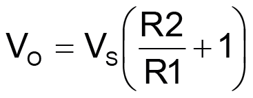
at D = 100%.
Some of these circuits establish a linear functionality between D and VO. Figure 1 is an example of that genre as described in “PWM buck regulator interface generalized design equations” (Ref. 1).
 |
|
| Figure 1. | PWM programs VO linearly. |
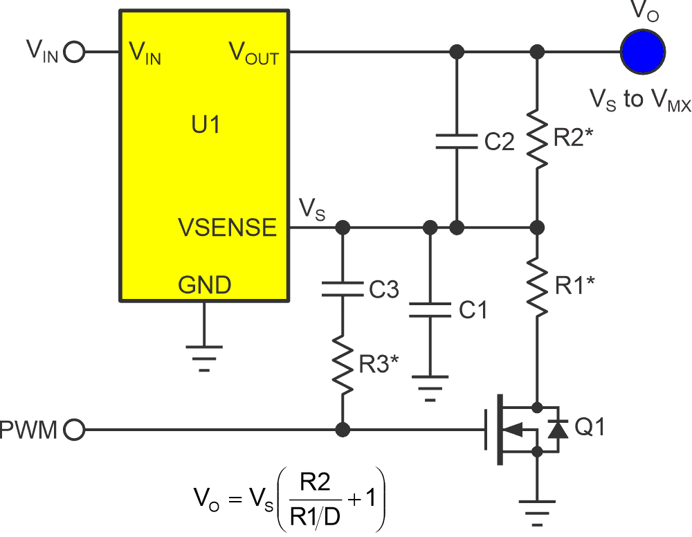
For others, like Figure 2’s concept designed by frequent contributor Christopher Paul and explained in “Improve PWM controller-induced ripple in voltage regulators” (Ref. 2)… it’s nonlinear…
 |
|
| Figure 2. | PWM programs VO nonlinearly. |
Note that for clarity, Figure 2 does not include many exciting details of Paul’s innovative design. See his article at the link for the whole story.
The nonlinearity problem
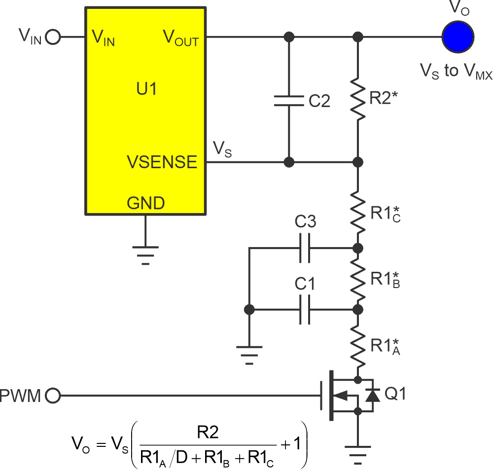
However, to explore the implications of Figure 2’s nonlinearity a bit further, in the example of the circuit provided in Paul’ DI (Ref. 2):
R1A = 2490 Ω
R1B = 2490 Ω
R1C = 4990 Ω
VS = 0.800 V
R2 = 53600 Ω
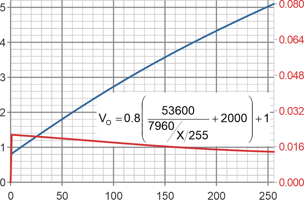
Which, if we assume 8-bit PWM resolution, provides the response curves shown in Figure 3.
 |
|
| Figure 3. | The 8-bit PWM setting versus D = X/255. The left axis (blue curve) is VO. The right axis (red curve) is VO volts increment per PWM least significant bit (LSBit) increment. |
Paul says of this nonlinear response: “Although the output voltage is no longer a linear function of the PWM duty cycle, a simple software-based lookup table renders this a mere inconvenience. (Yup, ‘we can fix it in software!’)” Of course, he’s absolutely right: For any chosen VO, a corresponding D can be easily calculated and stored in a small (256-entry) lookup table.
However, translating from the computed D to an integer 8-bit PWM code is a different matter. Figure 3’s increment-vs-increment red curve provides an important caveat to Paul’s otherwise accurate statement.
If the conversion from 8-bit 0 to 255 code to the 0.8 V to 5.1 V, or 4.3 V VO span, were linear, then each LSBit increment would bump VO by a constant 15.8 mV (= 4.3 V/256). But it isn’t.
And, as Figure 3’s red curve shows, due to the strong nonlinearity of the conversion, the 8-bit resolution criterion is exceeded for all PWM codes < 75 and VO < 3.77 V = 74% of full scale.
And it gets worse: For VO values down near VS = 0.8 V, the LSBit increment soars to 67 mV (= 4.3 V/64). This, therefore, equates to a resolution of not 8 bits, but barely 6.
The fix
Unfortunately, there’s very little any software fix can do about that. Which might make nonlinearity for some applications perhaps more than just an “inconvenience?” So what could fix it?
The nonlinearity basically arises from the fact that only a fraction (R1A) of the total R1ABC resistance is modulated by PWM, as the PWM D changes, that fraction changes, which in turn changes the rate of change of VO versus D. In fact, it changes this by quite a lot.
Getting to specifics, in the example of Paul’s circuit provided in his DI, we see they make the modulated resistance R1A only 25% of the total R1 resistance at D = 100%, with this proportion increasing to 100% as D goes to 0%. This is obviously a big change concentrated toward lower D.
A clue to a possible (at least partial) fix is found back in the observation that the nonlinearity and resolution loss originally arose from the fact that only a small fraction (25% R1A) of the total R1ABC resistance is modulated by PWM. So, perhaps a bigger R1A fraction of R1ABC could recover some of the lost resolution.
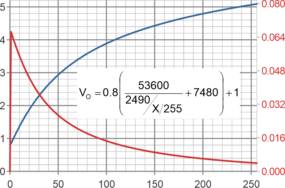
As an experiment, I changed Paul’s R1 resistor values to the following:
R1A = 7960 Ω
R1B = 1000 Ω
R1C = 1000 Ω
This makes R1A now 80% of R1ABC instead of only 25%. Figure 4 illustrates the effect on the response curves.
Figure 4’s blue VO versus PWM curve is obviously still nonlinear, but significantly less so. But perhaps the more important improvement is to the red curve: Unlike the previous erosion of resolution at the left end of the curve to 67 mV per PWM LSBit to just 6 bits, Figure 3 maxes out at 21 mV, or 7.7 bits.
 |
|
| Figure 4 | The impact of making R1A 80% of R1ABC. The left axis (blue curve) is VO. The right axis (red curve) is VO volts increment per PWM LSBit increment. |
Is this a “fix?” Well, obviously, 7.7 bits is better than 6 bits, but it’s still not 8 bits, so resolution recovery isn’t perfect. Also, my arbitrary shuffling of R1 ratios is almost certain to adversely impact the spectacular ripple attenuation cited in Christopher Paul’s original article. Mid-frequency loop gain may also suffer from the heavier loading on C2 and R2 imposed by the reduced R1C value. This could lead to a possible deterioration of the transient response and noise rejection. Perhaps C2 could be increased to moderate that effect.
Still, it would be fair to call it a start at a fix for nonlinearity that lay beyond the reach of software.
References
- Woodward, Stephen. "PWM buck regulator interface generalized design equations."
- Paul, Christopher. "Improve PWM controller-induced ripple in voltage regulators."